
Washing machine

A washing machine and whole machine technology, applied in the field of washing machines, can solve the problems of large occupied space, complicated wiring, large washing machine cost, etc., and achieve the effect of convenient drainage

Active Publication Date: 2021-06-01
HISENSE(SHANDONG)REFRIGERATOR CO LTD
View PDF8 Cites 0 Cited by
  • Summary
  • Abstract
  • Description
  • Claims
  • Application Information

AI Technical Summary

Problems solved by technology

[0002] Washing machines have been widely used as household appliances in people's lives. Generally, a family only has one washing machine. With the improvement of people's quality of life, classified and healthy cleaning has become a lifestyle and pursuit. Users usually increase the number of washing machines. However, multiple washing machines cost a lot, take up a lot of space, and have high maintenance costs. Therefore, double-drum and multi-drum washing machines with more than double drums have emerged as the times require, realizing the washing of clothes in separate drums
[0003] At present, most of the double-tubular washing machines are drained from the bottom. When the position of the drain port set by the user is high, the washing machine cannot be used, which makes the scope of application of the washing machine small, unable to meet the needs of different users, and makes the user experience poor; When the water outlet of the whole machine is blocked, the water discharged from the upper drum enters the lower drum and causes cross-contamination. The use of a one-way valve can prevent water from entering the lower drum, but the cost of setting the one-way valve is high, it needs to be controlled separately, and the circuit is complicated

Method used


Image

  • Washing machine
  • Washing machine
  • Washing machine

Examples


Embodiment Construction

[0041] In the following, the present invention will be specifically described through exemplary embodiments. It should be understood, however, that elements, structures and characteristics of one embodiment may be beneficially incorporated in other embodiments without further recitation.

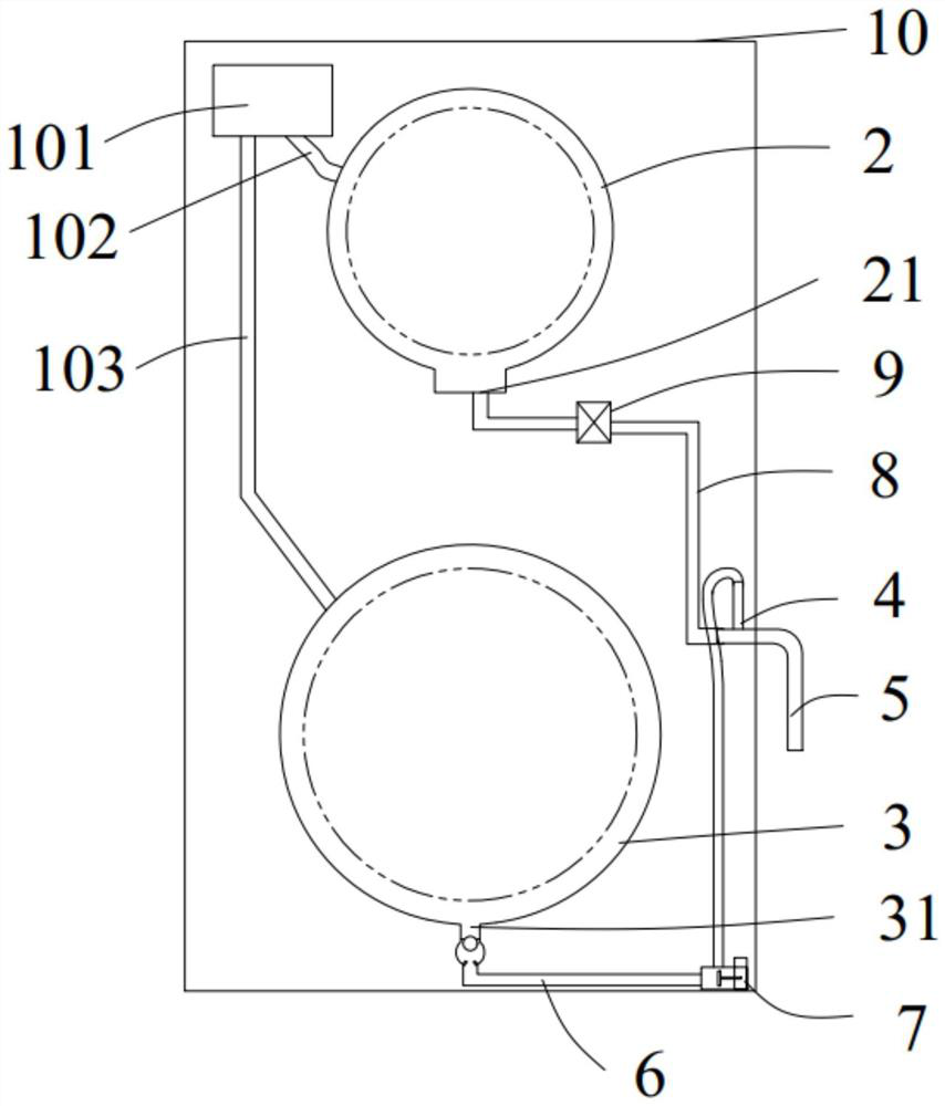
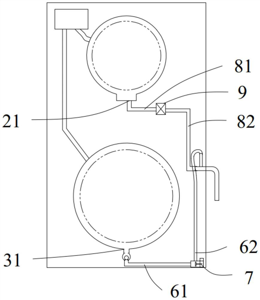
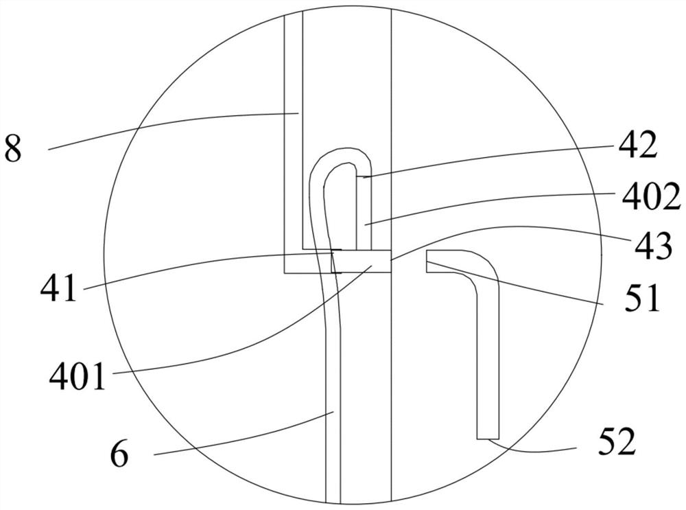
[0042] The present invention proposes a washing machine, as follows Figure 1-Figure 6 The washing machine is described, where Figure 1-Figure 2 Schematic diagram of the structure of the washing machine, image 3 A schematic diagram of the local structure of the washing machine.

[0043] Washing machine comprises casing 10, and casing 10 forms the appearance of main body of washing machine, and casing 10 comprises front side, back side, left side, right side, is located at the top board of casing 10 tops and is positioned at the base of casing 10 bottoms; An inlet for laundry is formed on the front side.

[0044] It should be noted that the front side mentioned here refers to the side f...


PUM


Abstract

The invention provides a washing machine. The washing machine comprises a machine shell, a first roller, a second roller, a complete machine drainage pipe and a floating ball structure; the first roller is arranged in the machine shell, and a first drainage port is formed in the bottom of the first roller; the second roller and the first roller are arranged up and down, the second roller is located below the first roller, and a second drainage port is formed in the bottom of the second roller; the complete machine drainage pipe is connected with the first drainage port and the second drainage port and used for draining washing water in the first roller and the second roller out of the washing machine; and the floating ball structure is connected between the second drainage port and the complete machine drainage pipe and used for communicating or isolating the second drainage port and the complete machine drainage pipe. By arranging the floating ball structure, the second drainage port and the whole machine drainage pipe can be communicated and blocked according to needs, external water can be prevented from entering the second roller through the second drainage port, especially when the whole machine drainage pipe is blocked, washing water in the first roller can be prevented from entering the second roller, cross contamination is avoided, and the structure is simple and feasible, and the cost is low.

Description

technical field [0001] The invention belongs to the technical field of washing machines, in particular to a double cylinder washing machine. Background technique [0002] Washing machines have been widely used as household appliances in people's lives. Generally, a family only has one washing machine. With the improvement of people's quality of life, classified and healthy cleaning has become a lifestyle and pursuit. Users usually increase the number of washing machines. However, multiple washing machines cost a lot, take up a lot of space, and have high maintenance costs. Therefore, double-drum and multi-drum washing machines with more than double drums have emerged as the times require, realizing the washing of clothes in separate drums. [0003] At present, most of the double-tubular washing machines are drained from the bottom. When the position of the drain port set by the user is high, the washing machine cannot be used, which makes the scope of application of the wash...

Claims


Application Information

Patent Timeline
Patent Type & Authority Applications(China)
IPC IPC(8): D06F39/08
CPCD06F39/083
Inventor 薛威海刘玉春刘振华陈贺宋子元
Owner HISENSE(SHANDONG)REFRIGERATOR CO LTD
Learn More