
Novel lifting type positioning device for movable workbench of press machine

A technology for moving workbenches and positioning devices, which is applied to presses, manufacturing tools, etc. It can solve problems such as the inability to meet the replacement of molds, the inability to meet the positioning requirements of two-way actuation of the workbench, and achieve the effect of realizing the positioning requirements

Pending Publication Date: 2021-06-04
JIER MACHINE TOOL GROUP
View PDF0 Cites 0 Cited by
  • Summary
  • Abstract
  • Description
  • Claims
  • Application Information

AI Technical Summary

Problems solved by technology

As the user's requirements for production efficiency increase, the ordinary one-way mobile workbench cannot meet the user's needs for mold replacement. As a high-efficiency mold change tool, the two-way actuated mobile workbench has the advantages of low cost and less resource consumption. It can meet the needs of users to conveniently switch between multiple mold changing stations
However, due to the two-way movement of the mobile workbench, the ordinary fixed raised workbench positioning device can only meet the positioning requirements of a single direction of the workbench because it protrudes from the moving plane of the workbench, and cannot meet the positioning requirements of the workbench’s two-way movement.

Method used


Image

  • Novel lifting type positioning device for movable workbench of press machine
  • Novel lifting type positioning device for movable workbench of press machine
  • Novel lifting type positioning device for movable workbench of press machine

Examples


Embodiment Construction

[0020] The present invention will be described in detail below in conjunction with the accompanying drawings and embodiments.

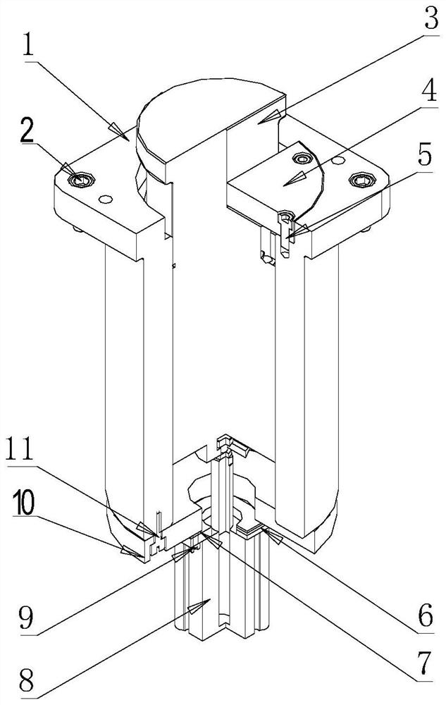
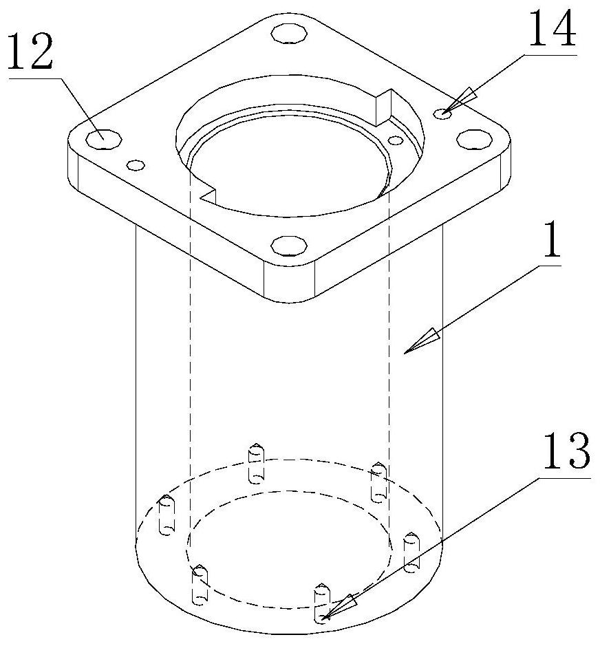
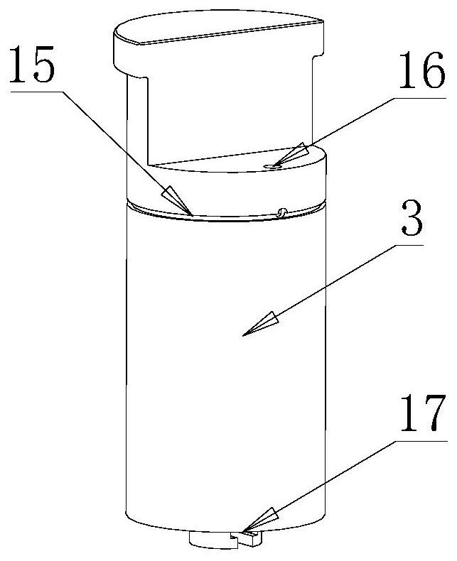
[0021] Such as Figure 1-Figure 8 As shown, the present invention provides a new type of lifting positioning device for the mobile workbench of a press, including a mounting base 1, a bumper body 3, an end cover 4, a lower adjustment pad 6, an upper adjustment pad 7, a cylinder 8 and a flange 10. The main body of the mounting seat 1 is a cylindrical structure connected up and down. The upper end of the mounting seat 1 is provided with a fixing screw hole 12 and a lifting hole 14, and the lower end is provided with a fixing screw hole 2 13. The mounting seat 1 is passed through the screw 1. 2. Through the fixing screw hole 12, it is fixed above the moving plane of the workbench; the bumper body 3 is installed in the cylinder body of the mounting base 1, and the end cover 4 is fixed in the mouth surface of the upper end of the mounting base 1 by screw 2...


PUM


Abstract

The invention discloses a novel lifting type positioning device for a movable workbench of a press machine. The device comprises a mounting base, a collision block body, an end cover, a lower adjusting pad, an upper adjusting pad, an air cylinder and a flange plate, the mounting base is of a vertically-through barrel structure, a first fixing screw hole and a lifting hole are formed in the upper end of the mounting base, a second fixing screw hole is formed in the lower end of the mounting base, the mounting base is fixed above a moving plane of the workbench, the collision block body is mounted in a mounting base barrel body, and the end cover is fixed in a spigot surface at the upper end of the mounting base so that the collision block body can be positioned when being lifted. The flange plate is fixed below the mounting base, the air cylinder is fixed on the flange plate, and the lower adjusting pad and the upper adjusting pad are mounted between the air cylinder and the mounting surface of the flange plate. A protruding head is arranged at the front end of a moving piston on the air cylinder, and a magnetic switch is arranged in a cylinder body. According to the moving direction of the movable workbench, the collision block body ascends or descends by controlling air inlet and air exhaust of the air cylinder, and the positioning requirement of the movable workbench during two-way starting is met.

Description

technical field [0001] The invention relates to a novel lift-type positioning device for a movable workbench of a press, which is applied in the press industry and belongs to the technical field of mechanical engineering. Background technique [0002] As an important part of the overall structure of the press, the mobile worktable is usually equipped with a worktable above it, and a T-shaped slot is opened on the top of the table to fix the lower mold or mold base, which is convenient for the user to replace the mold. As the user's requirements for production efficiency increase, the ordinary one-way mobile workbench cannot meet the user's needs for mold replacement. As a high-efficiency mold change tool, the two-way actuated mobile workbench has the advantages of low cost and less resource consumption. It can satisfy users to conveniently switch between multiple mold changing stations. However, due to the two-way movement of the mobile workbench, the ordinary fixed raised ...

Claims


Application Information

Patent Timeline
Patent Type & Authority Applications(China)
IPC IPC(8): B30B15/00
CPCB30B15/0041B30B15/0088
Inventor 吴义伟解付新陈璇吴雨东徐霞刘新颖
Owner JIER MACHINE TOOL GROUP
Learn More