A Pneumatic Single Droplet Generator

A generator, pneumatic technology, applied in printing and other directions, can solve the problem of inability to extrude a single droplet, and achieve the effect of preventing the loss of liquid, wide application prospects, and reasonable adjustment.

Active Publication Date: 2022-04-01
HUAZHONG UNIV OF SCI & TECH
View PDF6 Cites 0 Cited by
  • Summary
  • Abstract
  • Description
  • Claims
  • Application Information

AI Technical Summary

Problems solved by technology

[0003] In view of the above defects or improvement needs of the prior art, the present invention provides a pneumatic single droplet generator, the purpose of which is to make the liquid squeeze out from the pinhole under the impact by feeding pulse gas into the liquid chamber, and the pulse The gas is discharged from the gas outlet to generate a negative pressure in the liquid container, and the liquid is sucked back into the liquid chamber under the negative pressure, thereby forming a single droplet extrusion, thereby solving the problem that the single droplet extrusion cannot be realized by pneumatics in the prior art technical problem

Method used


Image

  • A Pneumatic Single Droplet Generator
  • A Pneumatic Single Droplet Generator

Examples


Embodiment Construction

[0024] In order to make the object, technical solution and advantages of the present invention clearer, the present invention will be further described in detail below in conjunction with the accompanying drawings and embodiments. It should be understood that the specific embodiments described here are only used to explain the present invention, not to limit the present invention. In addition, the technical features involved in the various embodiments of the present invention described below can be combined with each other as long as they do not constitute a conflict with each other.

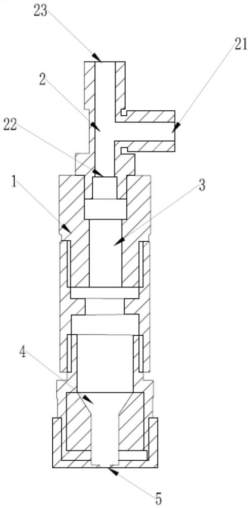
[0025] see figure 1 , the present invention proposes a pneumatic single droplet generator, which includes a generator body 1 and a connector 2 , a connection 3 and a liquid chamber 4 arranged in the generator body 1 .

[0026] The joint part 2 is a T-shaped three-way joint, the vertical nozzles are the gas outlet 23 and the communication port 22 respectively, and the horizontal nozzles are the ...


PUM


Abstract

The invention discloses a pneumatic single droplet generator, belonging to the technical field of fluid mechanics, comprising a generator body, a joint, a connecting piece and a liquid chamber; the joint includes a gas inlet, a communication port and a gas outlet; the connecting piece The lower end is connected to the liquid chamber, and the bottom of the liquid chamber is provided with a pinhole; the pulse gas is passed into the gas inlet, and the pulse gas enters the liquid chamber along the connector through the connecting piece, and the liquid in the liquid chamber is impacted by the pulse gas After being extruded from the pinhole, the pulse gas is discharged from the gas outlet to generate a negative pressure in the liquid cavity, and then the liquid is sucked back into the liquid cavity to realize the extrusion of a single droplet. In the present invention, the liquid is extruded from the pinhole under the impact by feeding the pulse gas, and at the same time, the pulse gas is discharged to generate a negative pressure in the liquid container, and the liquid is sucked back into the liquid cavity to realize the extrusion of a single droplet; and through The electromagnetic valve is controlled to realize the reasonable adjustment of the pulse gas pressure and pulse gas action time in the generator.

Description

technical field [0001] The invention belongs to the technical field of fluid mechanics, and more specifically relates to a pneumatic single droplet generator. Background technique [0002] In the prior art, there are mainly two types of single droplet generators. One is that inkjet printers use piezoelectric ceramics to generate pulse pressure to extrude a single droplet. The droplet diameter produced by this droplet generator is between Below 20 microns; the other is to drop from a needle tube. The diameter of the droplets produced by this droplet generator is about 2.5 mm, and the diameter of the droplets cannot be adjusted. Contents of the invention [0003] In view of the above defects or improvement needs of the prior art, the present invention provides a pneumatic single droplet generator, the purpose of which is to make the liquid squeeze out from the pinhole under the impact by feeding pulse gas into the liquid chamber, and the pulse The gas is discharged from the...

Claims


Application Information

Patent Timeline
Patent Type & Authority Patents(China)
IPC IPC(8): B41J2/045
CPCB41J2/04501
Inventor 崔岩李海
Owner HUAZHONG UNIV OF SCI & TECH
Why Eureka
Try Eureka