Wire arranging device for winding of transformer iron core

A technology of transformer iron core and wire management device, which is applied in inductance/transformer/magnet manufacturing, coil manufacturing, electrical components, etc., can solve the problems of transformer coils that are not wound neatly, copper wires cannot be arranged, and transformer quality is not up to standard, etc. To achieve the effect of avoiding reverse buckle and avoiding loosening

Pending Publication Date: 2021-06-04
王小英
View PDF0 Cites 0 Cited by
  • Summary
  • Abstract
  • Description
  • Claims
  • Application Information

AI Technical Summary

Problems solved by technology

[0005] In order to overcome the shortcomings that the existing winding equipment cannot arrange the copper wires, resulting in the coils of many transformers not being neatly wound, and the quality of the transformers is not up to standard, the technical problem of the present invention is to provide a method that can clean the copper wires during winding. A wire management device for winding transformer cores to improve the quality of the transformer

Method used


Image

  • Wire arranging device for winding of transformer iron core
  • Wire arranging device for winding of transformer iron core
  • Wire arranging device for winding of transformer iron core

Examples


Embodiment 1

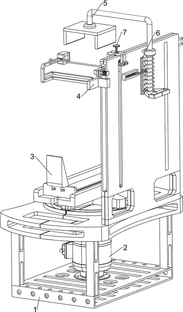
[0022] A wire management device for transformer core winding, such as Figure 1-5 As shown, it includes a base 1, a rotating assembly 2, a clamping assembly 3 and a cable management assembly 4. The base 1 is provided with a rotating assembly 2 that rotates by rotating, and the rotating assembly 2 is provided with a clamping assembly that slides. The clamping assembly 3 is tight, and the base 1 is provided with a wire management assembly 4 for wire management by sliding.

[0023] When using this device, the staff first puts the transformer body on the clamping assembly 3 and fixes it. After putting it in place, the staff starts the rotating assembly 2, and the rotating assembly 2 drives the clamping assembly 3 to rotate for winding. At the same time, the copper wires can be sorted through the wire management assembly 4 .

[0024] Such as figure 1 and figure 2 As shown, the rotating assembly 2 includes a geared motor 21, a rotating rod 22, a circular guide rail 23, an arc-sh...

Embodiment 2

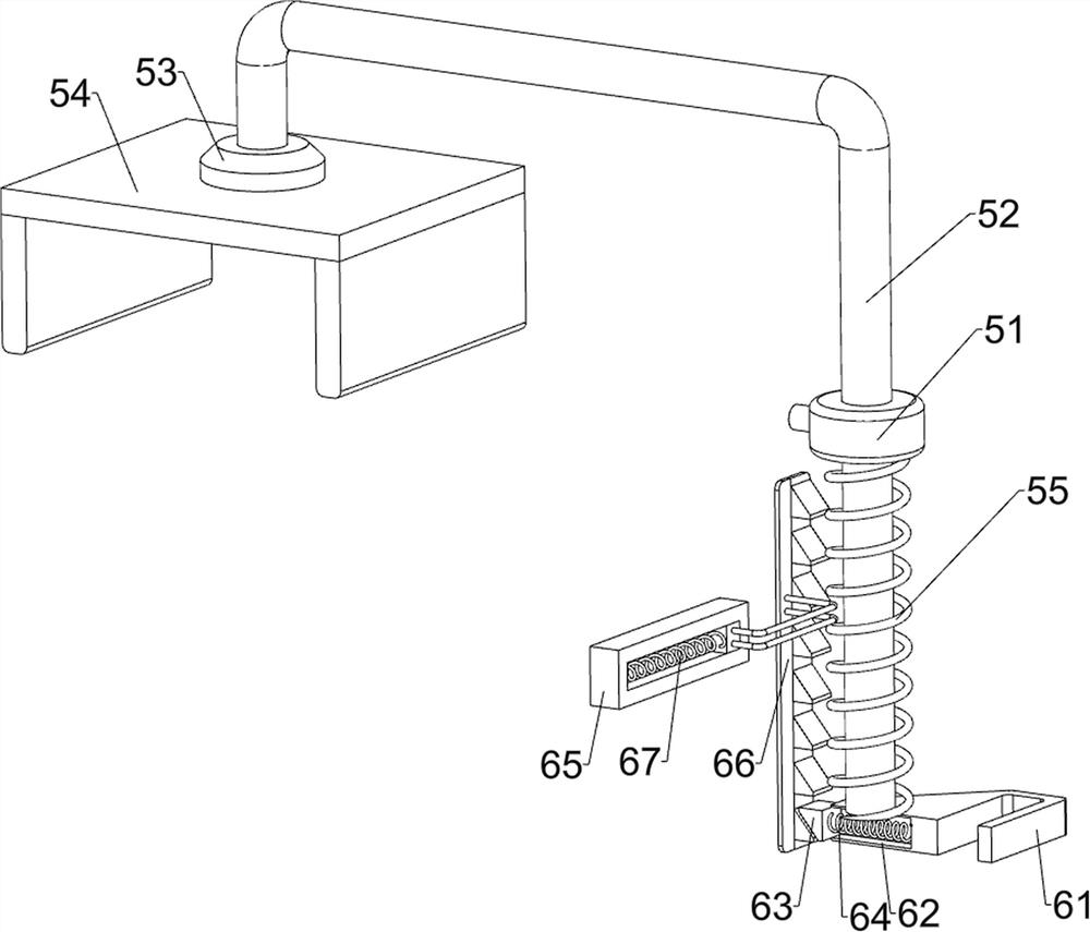
[0031] On the basis of Example 1, such as figure 1 and Figure 4 As shown, a fixed assembly 5 is also included, and the fixed assembly 5 includes a sliding sleeve 51, a sliding rod 52, a circular block 53, a U-shaped plate 54 and a fifth spring 55, and the upper right side of the base 1 is provided with a sliding sleeve 51. Sliding type is provided with slide bar 52 in cover 51, and the rotary type on slide bar 52 is provided with circular block 53, and circular block 53 is provided with U-shaped plate 54, and is wound around between slide bar 52 and sliding sleeve 51 and is connected with the fifth. Spring 55.

[0032] When using this device, before placing the transformer, the staff first pushes the sliding rod 52 to slide upward in the sliding sleeve 51, the fifth spring 55 is compressed, and the sliding rod 52 moves upward through the circular block 53 to drive the U-shaped plate 54 to move upward After the transformer is put away, the staff releases the sliding rod 52, ...


PUM


Abstract

The invention relates to a wire arranging device, in particular to a wire arranging device for winding of a transformer iron core. The wire arranging device can arrange copper wires in the winding process and improve the quality of a transformer. The wire arranging device comprises a base; a rotating assembly which is mounted on the base and rotates in a rotating manner; a clamping assembly which is mounted on the rotating assembly and is used for clamping in a sliding manner; and a wire arranging assembly which is mounted on the base and is used for arranging wires in a sliding manner. Power can be provided during winding through the rotating assembly, a transformer needing to be wound can be placed through the clamping assembly, a copper wire can be driven to move up and down through the wire arranging assembly during winding, a coil can be wound more smoothly, the transformer can be further fixed through the fixing assembly, and copper wires can be arranged during winding through the guiding assembly, so that the copper wires are prevented from being reversely buckled.

Description

technical field [0001] The invention relates to a wire management device, in particular to a wire management device for transformer iron core winding. Background technique [0002] A transformer is an electromagnetic device that works on the principle of electromagnetic induction. It is a static electrical device that converts one form of alternating current energy into another form of alternating current energy according to the principle of electromagnetic induction. [0003] During the production process of the transformer, it needs to be wound, and when winding, the coils must be wound neatly and aligned, and the copper wires must not be knotted and reversed. At present, the existing winding equipment cannot arrange the copper wires, which leads to the coils of many transformers not being wound neatly, and the quality of the transformers is not up to standard. [0004] Therefore, it is necessary to invent a kind of winding device for transformer iron core that can arrang...

Claims


Application Information

Patent Timeline
IPC IPC(8): H01F41/06H01F41/09H01F41/096
CPCH01F41/06H01F41/09H01F41/096
Inventor 王小英
Owner 王小英
Why Eureka
Try Eureka