Coating tool and coating method

A tool and coating technology, applied in the direction of surface coating liquid device, coating, pretreatment surface, etc., can solve the problems of difficult installation, large installation space, difficult to operate advance and retreat regulators, etc.

Pending Publication Date: 2021-06-04
菱技精密工具株式会社
View PDF7 Cites 2 Cited by
  • Summary
  • Abstract
  • Description
  • Claims
  • Application Information

AI Technical Summary

Problems solved by technology

Sometimes it is difficult to install due to the large installation space required, and it is difficult to operate the advance and retreat adjuster during coating
And, it is difficult to visually recognize the part to be coated with the coating liquid of the object to be coated (hereinafter referred to as the coating part).

Method used


Image

  • Coating tool and coating method
  • Coating tool and coating method
  • Coating tool and coating method

Examples


no. 1 Embodiment approach >

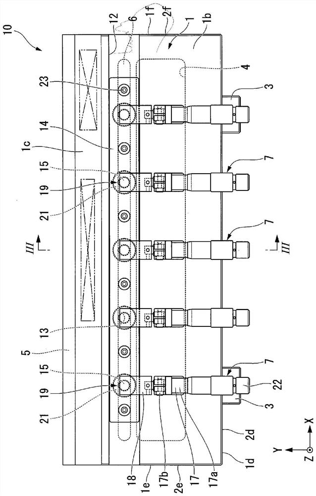
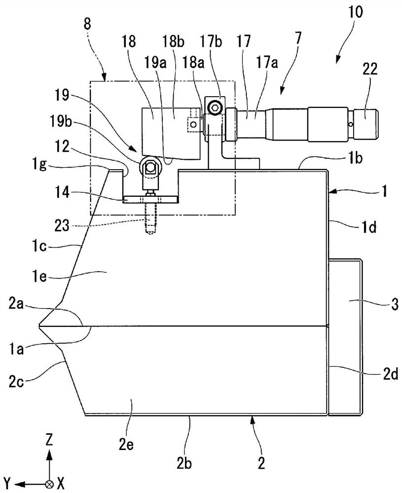
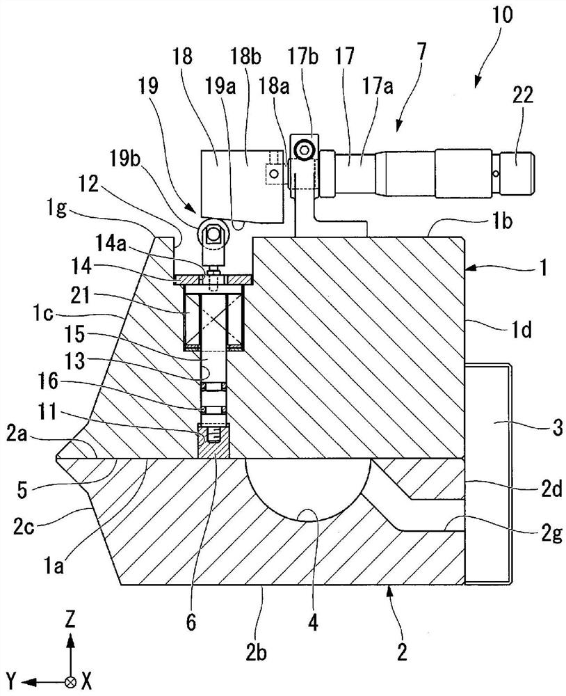
[0065] Below, refer to Figure 1 to Figure 5 , the coating tool 10 according to the first embodiment of the present invention will be described.

[0066] The coating tool 10 of the present embodiment is, for example, a so-called roll-to-roll (ROLL TO ROLL) slot die for coating a coating liquid on the surface of a film, metal foil, or other object to be coated.

[0067] Such as Figure 1 to Figure 5 As shown, the coating tool 10 of this embodiment includes a first head member 1, a second head member 2, a spacer member (not shown), a positioning block 3, a manifold 4, a slot 5, and a throttle rod. 6. The adjustment mechanism 7 and the cover body 8 .

[0068] The first head member 1 and the second head member 2 each have a substantially rectangular plate shape or a substantially cuboid shape. The first head member 1 and the second head member 2 are arranged adjacent to each other with their inner surfaces facing each other.

[0069] [Definition of directions used in this embo...

no. 2 Embodiment approach >

[0169] Next, refer to Figure 6 ~ Figure 8 Next, the coating tool 20 according to the second embodiment of the present invention and a coating method for coating a coating liquid on an object to be coated using the coating tool 20 will be described. In addition, in the second embodiment, the same reference numerals are assigned to the same constituent elements as those in the first embodiment, and description thereof will be omitted.

[0170] In addition to the first head member 1, second head member 2, spacer member (not shown), positioning block 3, manifold 4, slot 5. In addition to the throttle rod 6, the adjustment mechanism 7 and the cover body 8, a coating film thickness detection mechanism (not shown) and a control unit (not shown) are also provided.

[0171] Furthermore, the configuration of the adjustment mechanism 7 of the applicator 20 is different from the configuration of the adjustment mechanism 7 of the applicator 10 described in the above embodiment.

[0172]...

no. 3 Embodiment approach >

[0197] Next, refer to Figure 9 ~ Figure 11 , the coating tool 30 according to the third embodiment of the present invention will be described. The structure of the applicator 30 of the third embodiment is partially different from the structure of the applicator 10 described in the first embodiment. In addition, in this embodiment, the same code|symbol is attached|subjected to the same component as the above-mentioned embodiment, and the description is abbreviate|omitted.

[0198] Such as Figure 9 ~ Figure 11 As shown, the applicator 30 of the present embodiment includes the first head member 1, the second head member 2, the spacer member (not shown), and the positioning block 3 included in the applicator 10 of the first embodiment. , the manifold 4, the slot 5, the throttle rod 6, the adjustment mechanism 7, and the cover 8 (not shown), a fixing portion 25 is also provided.

[0199] In addition, the configuration of the adjustment mechanism 7 of the applicator 30 is parti...


PUM


Abstract

The present invention is equipped with a first head member (1) and a second head member (2) which are positioned so as to be adjacent in a first direction and extend in a second direction which is perpendicular to the first direction, a slot (5) which opens to the outside from between the tip section of the first head member (1) and the tip section of the second head member (2) in a third direction which is perpendicular to both the first direction and the second direction, a choke bar (6) which extends in the second direction inside the first head member (1) and is capable of projecting into the slot (5) from the first direction, and an adjustment mechanism (7) for adjusting the amount by which the choke bar (6) projects into the slot (5), the adjustment mechanism (7) having a shaft (15) which extends in the first direction inside the first head member (1) and is secured to the choke bar (6), a moving part (18) capable of moving in the third direction relative to the first head member (1), and a cam part (19) for converting the movement of the moving part (18) in the third direction into movement of the shaft (15) in the first direction.

Description

technical field [0001] The invention relates to a coating tool and a coating method. [0002] This application claims to be based on the patent application No. 2018-232729 filed in Japan on December 12, 2018, the patent application No. 2019-034880 filed in Japan on February 27, 2019, and the patent application filed in Japan on December 3, 2019 Priority of No. 2019-218973, the contents of which are incorporated herein. Background technique [0003] Conventionally, a coating tool called a slot die or the like is known. In slot die coating (Slot Die Coating), as a method for uniformly discharging the coating liquid in the coating width direction, there is a method that allows a choke bar (Choke bar) to enter and exit the flow path and restrict it arbitrarily. A method of adjusting the discharge volume through the flow path. This method is used for extrusion molding, etc. like the T-die shown in Patent Document 1. In this T-die, the throttle lever is mainly operated using t...

Claims


Application Information

Patent Timeline
Patent Type & Authority Applications(China)
IPC IPC(8): B05D1/26B05D3/00B05C5/02
Inventor 林敦高桥健远藤惠彭瑶小仓荣次
Owner 菱技精密工具株式会社
Why Eureka
Try Eureka