
Automatic fertilizing device for agricultural planting

A fertilization device and automatic technology, which can be applied in the fields of fertilization device, agriculture, application, etc., can solve the problems of waste of fertilizer, time-consuming and laborious, and increase of fertilization cost.

Pending Publication Date: 2021-06-08
SHANGHAI INSTITUTE OF TECHNOLOGY
View PDF9 Cites 0 Cited by
  • Summary
  • Abstract
  • Description
  • Claims
  • Application Information

AI Technical Summary

Problems solved by technology

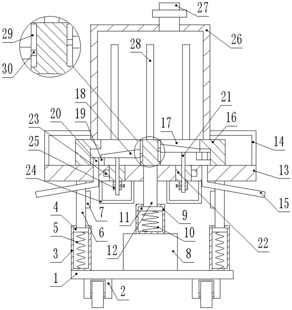
[0002] With the development of modern agriculture, fertilizers are becoming more and more important, and there are more and more fertilization tools and methods. Most of the existing fertilization devices are spread by pulling the fertilization box at the back by a power vehicle. It is convenient to fertilize, but when the crops grow up, because the vehicle cannot drive into the ground, a device commonly known as a gourd is usually used for fertilization, but this is time-consuming and laborious, and it cannot be automatically spread, which increases the labor intensity of the operators, and The distance between different types of crops is not the same, some are far apart, and some are relatively close, which cannot be adjusted effectively, thus wasting fertilizer and increasing the cost of fertilization

Method used


Image

  • Automatic fertilizing device for agricultural planting
  • Automatic fertilizing device for agricultural planting

Examples


Embodiment Construction

[0041] The present invention will be described in further detail below in conjunction with the accompanying drawings and specific embodiments. Advantages and features of the present invention will be apparent from the following description and claims. It should be noted that the drawings are all in a very simplified form and use imprecise ratios, which are only used to facilitate and clearly assist the purpose of illustrating the embodiments of the present invention.

[0042] It should be noted that all directional indications (such as up, down, left, right, front, back...) in the embodiments of the present invention are only used to explain the relationship between the components in a certain posture (as shown in the accompanying drawings). Relative positional relationship, movement conditions, etc., if the specific posture changes, the directional indication will also change accordingly.

[0043] see Figures 1 to 2 , the core of the present invention is to provide a kind ...


PUM


Abstract

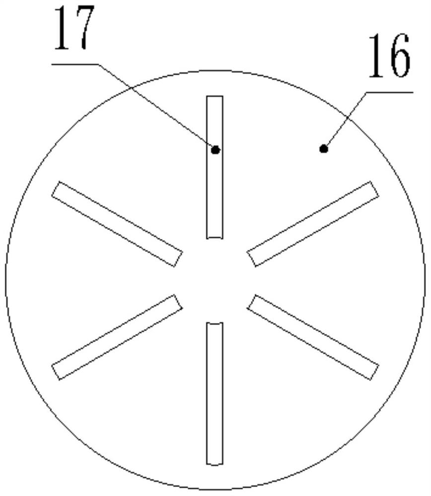
The invention discloses an automatic fertilizing device for agricultural planting. The automatic fertilizing device comprises a base, a plurality of vibration rods, a fixing plate, a rotating rod, a material distribution disc and a discharging box, wherein the lower ends of the vibration rods are connected with a first damping assembly; the first damping assembly is fixedly arranged on the base; a vibrator is arranged on each vibration rod; the fixing plate is fixedly arranged at the upper ends of the plurality of vibration rods; a plurality of discharging pipes are arranged on the fixing plate in a penetrating mode; the rotating rod penetrates through the fixing plate; the lower end of the rotating rod is connected with a second damping assembly; the lower end of the second damping assembly is connected to a driving device; the driving device is fixedly arranged on the base and is used for driving the second damping assembly to rotate; the second damping assembly drives the rotating rod to rotate; the material distribution disc is arranged at the upper end of the fixing plate and is fixedly connected with the rotating rod; the material distribution disc is provided with a plurality of discharging grooves in positions opposite to the discharging pipes; the rotating rod drives the material distribution disc to rotate so that the discharging grooves can be periodically overlapped with the discharging pipes; materials are stored in the discharging box; and the discharging box is arranged on the upper end surface of the material distribution disc, and communicates with the discharging grooves. The automatic fertilizing device for agricultural planting can realize automatic fertilization.

Description

technical field [0001] The invention belongs to the technical field of agricultural planting, in particular to an automatic fertilizing device for agricultural planting. Background technique [0002] With the development of modern agriculture, fertilizers are becoming more and more important, and there are more and more fertilization tools and methods. Most of the existing fertilization devices are spread by pulling the fertilization box at the back by a power vehicle. It is convenient to fertilize, but when the crops grow up, because the vehicle cannot drive into the ground, a device commonly known as a gourd is usually used for fertilization, but this is time-consuming and laborious, and it cannot be automatically spread, which increases the labor intensity of the operators, and The distance between different types of crops is not the same, some are far apart, and some are relatively close, which cannot be adjusted effectively, thus wasting fertilizer and increasing the co...

Claims


Application Information

Patent Timeline
IPC IPC(8): A01C15/12
CPCA01C15/12
Inventor 唐有绮陈喜陈文南王渤吴俊昊江宇阮思远
Owner SHANGHAI INSTITUTE OF TECHNOLOGY
Learn More