A device and method for automatically aligning and clamping ring-shaped parts

A ring-shaped, positive-loading technology, used in positioning devices, metal processing machinery parts, clamping and other directions, to improve processing efficiency, reduce parts clamping time, and reduce workpiece alignment time.

Active Publication Date: 2022-07-15
宜昌长机科技有限责任公司
View PDF7 Cites 0 Cited by
  • Summary
  • Abstract
  • Description
  • Claims
  • Application Information

AI Technical Summary

Problems solved by technology

[0007] In order to solve the above technical problems, the present invention provides an automatic aligning and clamping device and method for ring-shaped parts, which solves the problem of aligning and clamping large-sized ring-shaped parts, and the adjustment is very convenient

Method used


Image

  • A device and method for automatically aligning and clamping ring-shaped parts
  • A device and method for automatically aligning and clamping ring-shaped parts
  • A device and method for automatically aligning and clamping ring-shaped parts

Examples


Embodiment 1

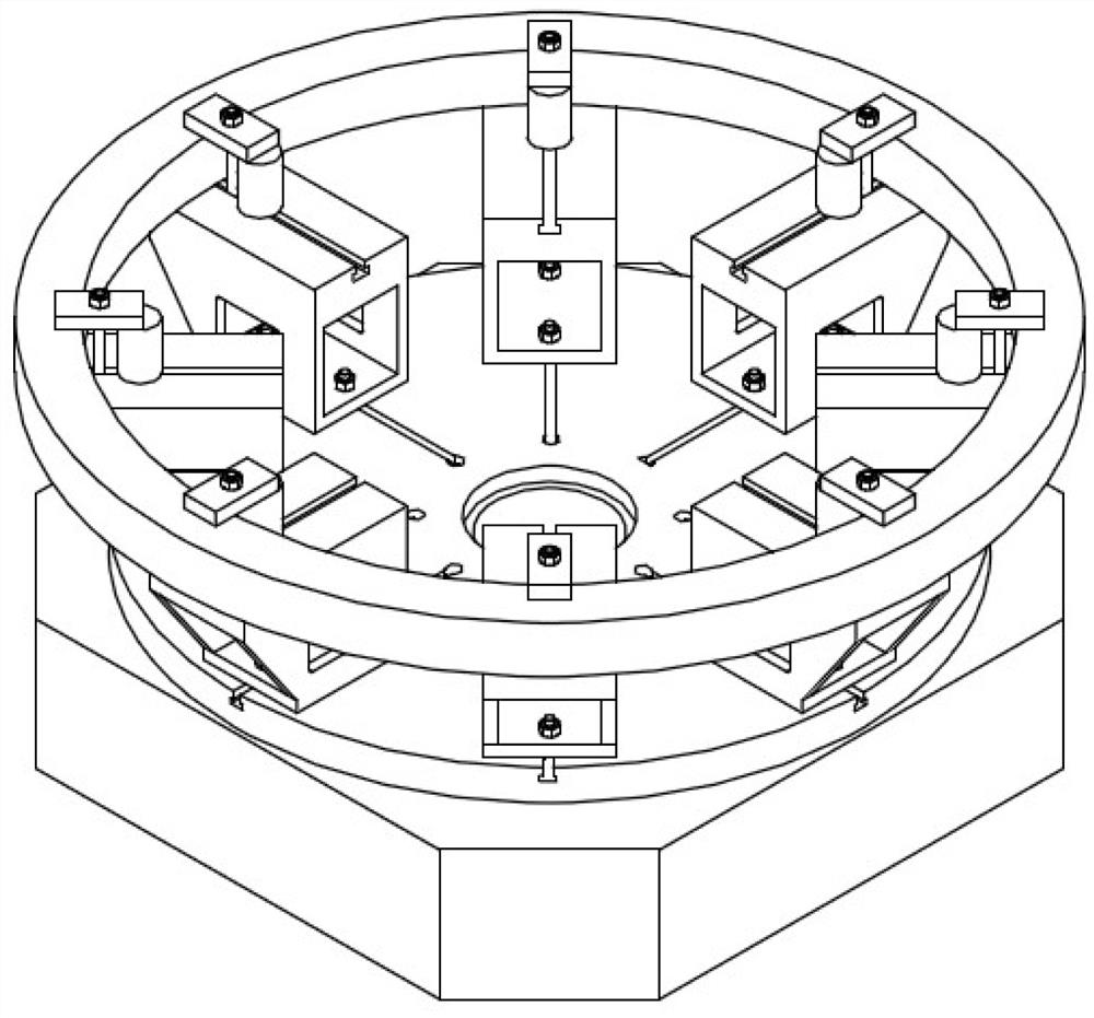
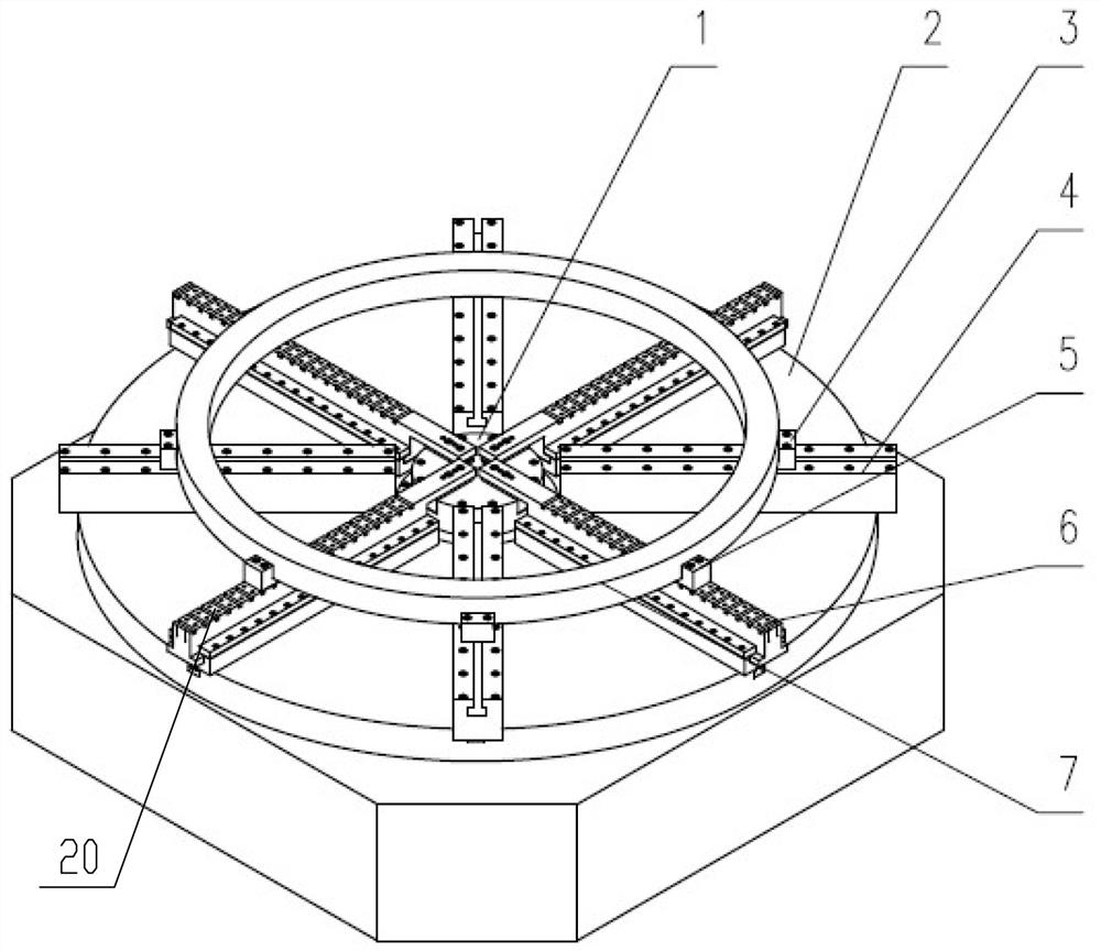
[0036] see Figure 2-4 , an automatic aligning and clamping device for ring-shaped parts, which includes a rotary table 2, a power chuck 1 is fixedly installed in the center of the rotary table 2; the rotary table 2 is located on the power chuck A plurality of radially arranged T-slots 18 are uniformly distributed on the periphery of the 1. A slide rail assembly 19 is fixed on the T-slot 18, and the slide rail 6 is installed on the slide rail assembly 19 through sliding fit. The inner end of the slide rail 6 is fixedly connected with the jaws 17 of the power chuck 1 through a fine-tuning mechanism, and synchronously drives the slide rail 6 under the contraction or unfolding action of the plurality of jaws 17; the top of the slide rail 6 is provided with There is a limit structure for limiting the workpiece. By adopting the automatic aligning and clamping device with the above structure, according to the diameter of the workpiece, the power chuck 1 of the appropriate size seri...

Embodiment 2

[0044] The method of using the automatic aligning and clamping device to align and clamp a ring-shaped part includes the following steps:

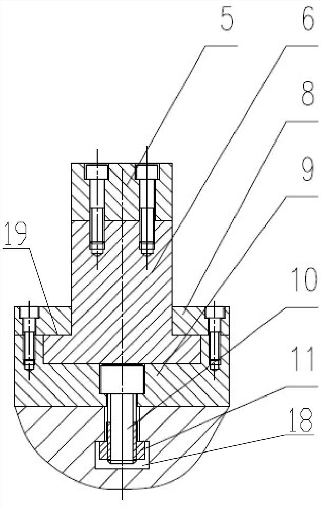
[0045] Step 1: According to the external dimensions of the workpiece 7, adjust the assembly position of the transition pad 14 on the jaw 17;

[0046] Step 2: After the position adjustment of the transition pad 14 is completed, the slide rail 6 is fixed to the correct position on the transition pad 14 by the cylindrical pin 13;

[0047] Step 3: Fasten the slide rail 6 to the jaw 17 through the screw 12;

[0048] Step 4: According to the different diameter and size ranges of the workpiece 7, the card holder 5 is arranged at the appropriate position of the card slot 20 on the slide rail 6;

[0049] Step 5: Activate the power chuck 1, contract the driving jaws 17 synchronously by the power chuck 1, then drive the slide rail 6 through the jaws 17, drive the card base 5 through the slide rail 6, and then drive the slide rail 6 by a plurality of s...


PUM


Abstract

The invention provides an automatic aligning and clamping device and method for ring-shaped parts, which comprises a rotary worktable, a power chuck is fixedly installed in the central part of the rotary worktable; the rotary worktable is located on the power chuck. A plurality of radially arranged T-shaped grooves are uniformly processed on the periphery of the disk. A sliding rail assembly is fixed on the T-shaped groove. A sliding rail is installed on the sliding rail assembly through sliding fit. The inner side of the sliding rail The end is fixedly connected with the jaws of the power chuck through a fine-tuning mechanism, and synchronously drives the slide rail under the contraction or expansion of multiple jaws; the top of the slide rail is provided with a limit structure for limiting the workpiece. . The problem of alignment and clamping of large-sized ring parts is solved, and the adjustment is very convenient.

Description

technical field [0001] The invention belongs to the field of annular workpiece clamping tooling, in particular to an automatic alignment and clamping device and method for annular parts, which is especially suitable for automatic alignment and clamping of annular parts whose diameters vary widely. Background technique [0002] see figure 1 , The existing clamping scheme for machining large ring-shaped parts is usually based on the size of the workpiece, arrange a corresponding number of parts support seats on the appropriate position of the machine tool table, and fix the part support seats on the machine tool table through T-bolts Then, manually align the workpiece to be processed and fix it on the support seat through the pressure plate. This solution can meet the machining requirements of ring-shaped parts of different sizes by adjusting the position of the part support seat on the table top of the machine tool, but the existing solution has the following disadvantages: ...

Claims


Application Information

Patent Timeline
Patent Type & Authority Patents(China)
IPC IPC(8): B23Q3/06B23Q3/18
CPCB23Q3/062B23Q3/18
Inventor 王维
Owner 宜昌长机科技有限责任公司
Why Eureka
Try Eureka