Electric welding gun device capable of automatically replacing welding rod and adjusting feeding speed

A technology of feed speed and automatic replacement, applied in the direction of electrode support device, electrode characteristics, welding equipment, etc., can solve the problems of reducing work efficiency, unstable clamping, affecting work quality, etc., so as to improve work efficiency and reduce work errors , the effect of improving the quality of work

Active Publication Date: 2020-10-30
上海中巽科技股份有限公司
View PDF6 Cites 6 Cited by
  • Summary
  • Abstract
  • Description
  • Claims
  • Application Information

AI Technical Summary

Problems solved by technology

[0002] Nowadays, electric welding has been widely used in various industrial sectors. The main form is still manual electric welding. Workers need to hold electric welding pliers to hold the welding rod to weld metal. Due to frequent replacement of welding rods, a lot of working time is wasted. The work efficiency is reduced. At the same time, when the welding rod is clamped by the welding tongs, the clamping instability and the poor control of the feed speed often lead to welding problems, which greatly affects the quality of work.

Method used


Image

  • Electric welding gun device capable of automatically replacing welding rod and adjusting feeding speed
  • Electric welding gun device capable of automatically replacing welding rod and adjusting feeding speed
  • Electric welding gun device capable of automatically replacing welding rod and adjusting feeding speed

Examples


Embodiment Construction

[0017] All features disclosed in this specification, or steps in all methods or processes disclosed, can be combined in any way, except for mutually exclusive features and or steps.

[0018] Combine below Figure 1-6 The present invention is described in detail, and for convenience of description, the orientations mentioned below are now stipulated as follows: figure 1 The up, down, left, right, front and back directions of the projection relationship itself are the same.

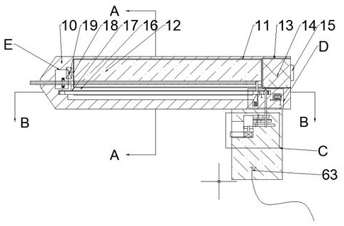
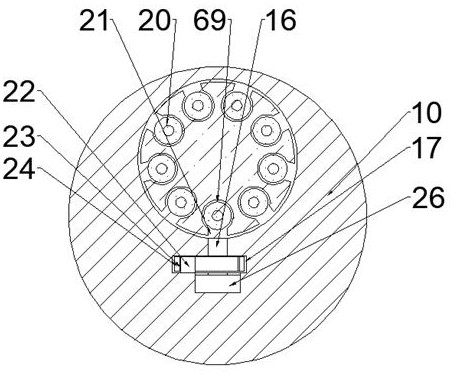
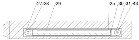
[0019] Such as Figure 1-6 As shown, an electric welding torch device with automatic electrode replacement and adjustable feeding speed of the device of the present invention includes a torch body 10, a roulette cavity 11 is arranged inside the torch body 10, and the right side of the roulette cavity 11 communicates with A cover cavity 13 with an opening to the right is provided. The cover cavity 13 is internally threaded and connected with a cover 14. The right end surface of the cover 14 is fixedly conn...


PUM


Abstract

The invention discloses an electric welding gun device capable of automatically replacing a welding rod and adjusting a feeding speed. The device comprises a gun body, wherein a wheel disc cavity is formed in the gun body, a cover body cavity with a rightward opening communicates with the right side of the wheel disc cavity, a cover body is in threaded fit connection with the interior of the coverbody cavity, a rotating block is fixedly connected to the right end face of the cover body, a push plate cavity communicates with the lower end wall of the wheel disc cavity, the lower end wall of the push plate cavity communicates with a delivery cavity, and the lower end wall of the delivery cavity communicates with a reset cavity. According to the device, automatic replacement of the welding rod is achieved through timing rotation of a wheel disc, the working time is saved to a great extent, the working efficiency is improved, meanwhile, a welding rod clamping function is achieved throughextrusion of a tip sliding block, a push plate is driven to move forwards through rotation of a conveying belt to achieve feeding of the welding rod, and the feeding speed is controlled by controllinga rotating speed of the conveying belt, so that working errors are reduced, and the working quality is improved.

Description

technical field [0001] The invention relates to the technical field related to welding rods, in particular to an electric welding torch device which can automatically replace welding rods and whose feed speed can be adjusted. Background technique [0002] Nowadays, electric welding has been widely used in various industrial sectors. The main form is still manual electric welding. Workers need to hold electric welding pliers to hold the welding rod to weld metal. Due to frequent replacement of welding rods, a lot of working time is wasted. Reduced work efficiency, at the same time, clamping the welding rod with the electric welding tongs often occurs that the clamping is unstable and the feed speed is not well controlled, which leads to problems in welding, which greatly affects the quality of work. Contents of the invention [0003] In view of the deficiencies of the above-mentioned technologies, the present invention proposes an electric welding torch device that automati...

Claims


Application Information

Patent Timeline
Patent Type & Authority Applications(China)
IPC IPC(8): B23K9/28B23K9/133
CPCB23K9/133B23K9/28
Inventor 叶艺芳
Owner 上海中巽科技股份有限公司
Why Eureka
Try Eureka