Profiling polishing equipment
A technology of equipment and profiling device, used in grinding/polishing equipment, metal processing equipment, grinding machines, etc., can solve the problems of long debugging time, poor grinding effect, inconvenient use, etc., to achieve good grinding effect and high production efficiency , the effect of stable quality
- Summary
- Abstract
- Description
- Claims
- Application Information
AI Technical Summary
Problems solved by technology
Method used
Image
Examples
Embodiment 1
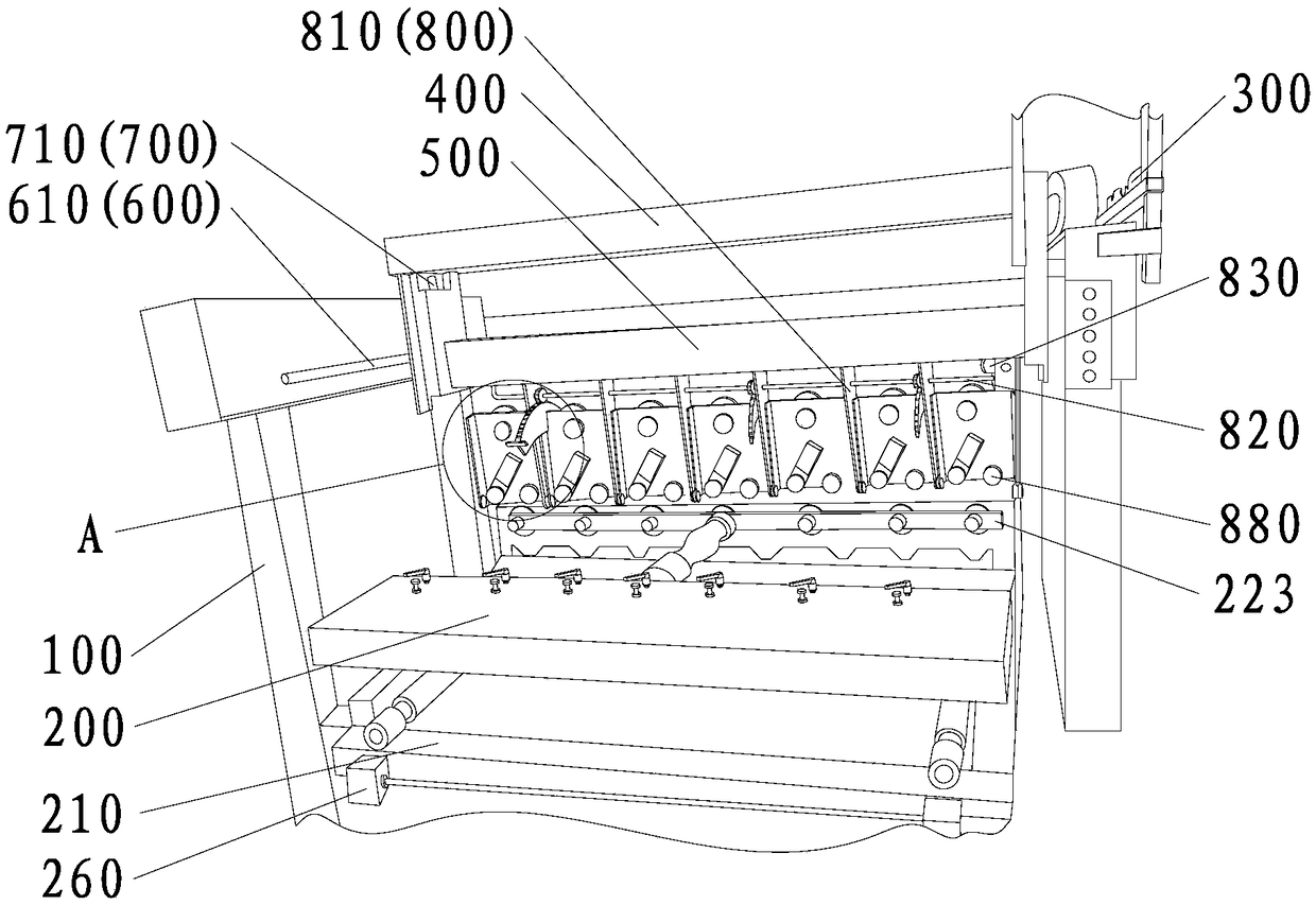
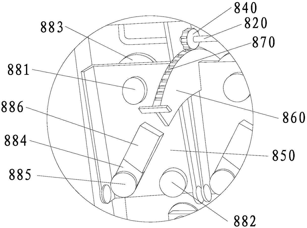
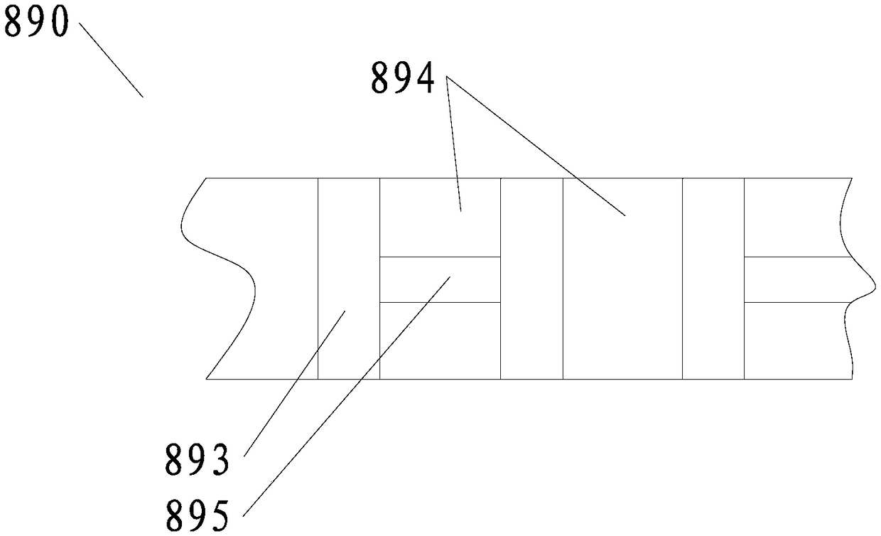
[0066] Such as Figure 1-Figure 6 As shown, the profiling polishing equipment provided in this embodiment includes a frame 100, a control module (not shown in the figure), a clamping table 200 and a profiling device 300 arranged on the frame 100, and a horizontal sliding connection The traversing frame 400 on the frame 100, the lifting frame 500 vertically slidably connected to the traversing frame 400, the traversing driving device 600 for driving the traversing frame 400 to move, the lifting frame for driving the lifting frame 500 to move The driving device 700 and the grinding main machine 800 arranged on the lifting frame 500, wherein the control module is a conventional module, which can be directly purchased from the market, is not the focus of this embodiment, and will not be described in detail here. It should be noted that the clamping workbench 200 in this embodiment can also be used in other stone processing equipment, and the grinding host 800 can also be used inde...
Embodiment 2
[0083] This embodiment provides a stone grinding machine. The main difference between the stone grinding machine and the profiling polishing equipment provided in Embodiment 1 is that the stone grinding machine provided in this embodiment is not equipped with a profiling device 300, which is about to be described in Embodiment 1. After the profiling device 300 of the profiling polishing equipment is removed, the stone grinding machine of this embodiment can be obtained. Of course, the specific parameter setting of the control module needs to be adjusted adaptively. The specific adjustment method is a conventional method, not this embodiment. The focus of the embodiment will not be described in detail here.
Embodiment 3
[0085] This embodiment mainly has the following differences from the first embodiment, and the structure is the same as that of the first embodiment except for the following differences.
[0086] First, if Figure 7 As shown, the structure of the grinding layer 892 of the flexible grinding belt 890 used in this embodiment is different from that of Embodiment 1. In this embodiment, the grinding layer 892 has a plurality of elliptical bumps 896, each elliptical The protrusions 896 are arranged irregularly, and a gap for chip removal is formed between two adjacent oval protrusions 896 .
[0087] Second, if Figure 8 As shown, the workbench frame 252 of the clamping workbench 200 in this embodiment is not provided with a connecting sleeve 256 and a screw rod 258, but an adjustment rod 910 is provided at a position between the two frame rods 255, and the two frames Adjusting sleeves 911 are respectively fixedly connected to the rod 255, and the two ends of the adjusting rod 910 a...
PUM
 Abstract
Description
Claims
Application Information
 - R&D
- Intellectual Property
- Life Sciences
- Materials
- Tech Scout
- Unparalleled Data Quality
- Higher Quality Content
- 60% Fewer Hallucinations
Browse by: Latest US Patents, China's latest patents, Technical Efficacy Thesaurus, Application Domain, Technology Topic, Popular Technical Reports.
© 2025 PatSnap. All rights reserved.Legal|Privacy policy|Modern Slavery Act Transparency Statement|Sitemap|About US| Contact US: help@patsnap.com


