Expansion rivet

A technology of expanding rivets and pins, which is applied in the direction of rivets, pins, screws, etc., and can solve problems such as creep

Pending Publication Date: 2021-06-08
A RAYMOND & CO
View PDF1 Cites 0 Cited by
  • Summary
  • Abstract
  • Description
  • Claims
  • Application Information

AI Technical Summary

Problems solved by technology

Another concern concerns the risk of creep on thin sections of the structure to be fastened due to the presence of a void between the two pieces

Method used


Image

  • Expansion rivet
  • Expansion rivet
  • Expansion rivet

Examples


Embodiment Construction

[0035] Different figures and components in the same figure are not necessarily shown to the same scale. In all figures, the same parts have the same reference numerals.

[0036] The terms used in this specification should under no circumstances be interpreted in a limiting or restrictive manner, merely as it is used in connection with the detailed description of certain embodiments of the invention.

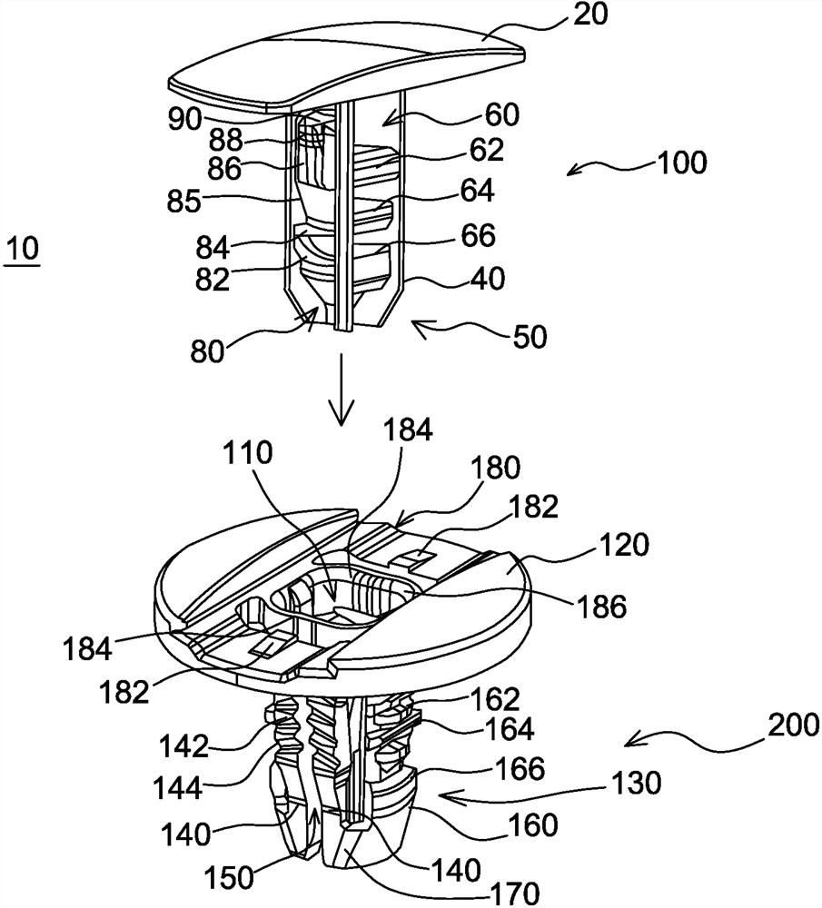
[0037] figure 1 An exploded view of the expansion rivet 10 according to the invention is shown, which essentially consists of a body 200 and a pin 100 . For illustrative purposes only, such as Figure 4D As shown, the device 10 may be used to fasten a first structure 300, such as an instrument panel, to a second structure 400, such as a vehicle body panel, as will be described in detail below. The first structure and the second structure are respectively provided with through holes to allow such fastening using the expansion rivets 10 .

[0038] The two basic parts 100, 200 o...


PUM


Abstract

An expansion rivet (10) comprises a body (200) and a pin (100), the body (200) has a bearing plate (120), forming a head with a passage opening (110), and two arms (130) projecting erectly from the bearing plate (120). Said pin (100) comprises a bearing head (20) with a lower surface (22) and a shank (50) projecting erectly from the bearing head (20), and the pin (100) is intended to be inserted into the body (200) through the opening (110) formed in the bearing plate (120), wherein the arms (130) each have a central fin (160) and two lateral fins (140) separated by a central fin; the shank (50) has flanges (40) over its length; the central fins (160) are capable of being parted outwardly in the radial plane by means of bulges (62, 64, 66) separating flanges (40); and the lateral fins (140) are capable of being deformed in the radial plane by the flanges (40) when the pin (100) is inserted into the body (200).

Description

technical field [0001] The present invention relates to a fastener, in particular a plastic rivet, and more particularly to an expansion rivet intended to be fastened in fastening holes formed on at least two structures. For example, trim parts of automobiles can be fastened to automobile body panels by means of the rivets of the present invention. Background technique [0002] An expansion rivet basically consists of a pin and a body, usually made of elastic material, so it can deform and retract for assembly and disassembly. Devices of this type are known from the prior art. [0003] US Patent No. 20150176621 A1 describes a rivet for vehicles consisting of an inner part and an outer part. The outer part comprises two spaced-apart separating arms comprising protrusions acting as snap protrusions on their outer surfaces. When the inner piece is inserted between the arms, the arms are deflected outward. The snap-in projection performs an engaging action on two diametrical...

Claims


Application Information

Patent Timeline
Patent Type & Authority Applications(China)
IPC IPC(8): F16B13/06F16B19/10
CPCF16B13/063F16B19/10F16B19/1081
Inventor 帕斯卡尔·加缪
Owner A RAYMOND & CO
Why Eureka
Try Eureka