Automobile tire wear test comparison device

A comparison device, a technology for automobile tires, applied in automobile tire testing, measuring devices, vehicle testing, etc., can solve problems such as test errors, low efficiency, and inability to accurately judge the degree of wear by visual observation.

Pending Publication Date: 2021-06-08
黄志传
View PDF0 Cites 4 Cited by
  • Summary
  • Abstract
  • Description
  • Claims
  • Application Information

AI Technical Summary

Problems solved by technology

[0006] In order to overcome the disadvantages that the tires need to be manually worn with abrasive paper, inconsistent manual strength control will cause test errors, and the degree of wear cannot be accurately judged by visual inspection, and the efficiency is low. The techni

Method used


Image

  • Automobile tire wear test comparison device
  • Automobile tire wear test comparison device
  • Automobile tire wear test comparison device

Examples


Embodiment 1

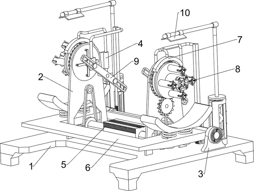
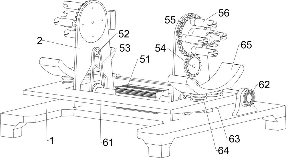
[0030] A kind of automobile tire wear test comparison device, such as figure 1 with figure 2 As shown, it includes a base 1, a support plate 2, a fixed plate 3, a fixed frame 4, a rotating assembly 5 and a friction assembly 6. The support plate 2 is connected to the left and right sides of the top of the base 1, and the left and right sides of the top of the base 1 are connected to The fixed plate 3 is connected with the fixed frame 4 on the rear side of the upper part of the supporting plate 2 on both sides, the rotating assembly 5 is connected in the middle of the top of the base 1, and the friction assembly 6 is connected in the upper part of the fixed plate 3 in a rotatable manner.

[0031] The rotating assembly 5 includes a biaxial motor 51, a rotating shaft 52, a belt 53, a full gear 54, a gear plate 55, and a positioning shaft 56, and the biaxial motor 51 is installed in the middle of the top of the base 1, and the inner sides of the support plates 2 on both sides are ...

Embodiment 2

[0035] On the basis of Example 1, such as image 3 As shown, a brake assembly 7 is also included. The brake assembly 7 includes a brake disc 71, a caliper 72 and a first carriage 73. The outer sides of the toothed discs 55 on both sides are connected with a brake disc 71. The fixed mounts 4 on both sides A caliper 72 is slidably connected to the middle part, and a first sliding frame 73 is connected to the front side of the calipers 72 on both sides, and the first sliding frame 73 is located directly above the brake disc 71 .

[0036] When the toothed discs 55 on both sides rotate, the first carriages 73 on both sides can be driven downward by manually pressing the calipers 72 on both sides, and the first carriages 73 on both sides move downward together with the brake discs 71 on both sides. The contact makes the toothed disc 55 stop rotating, so that it is more convenient when people want to stop and look at the tire status on both sides, and the rotation of the toothed disc...

Embodiment 3

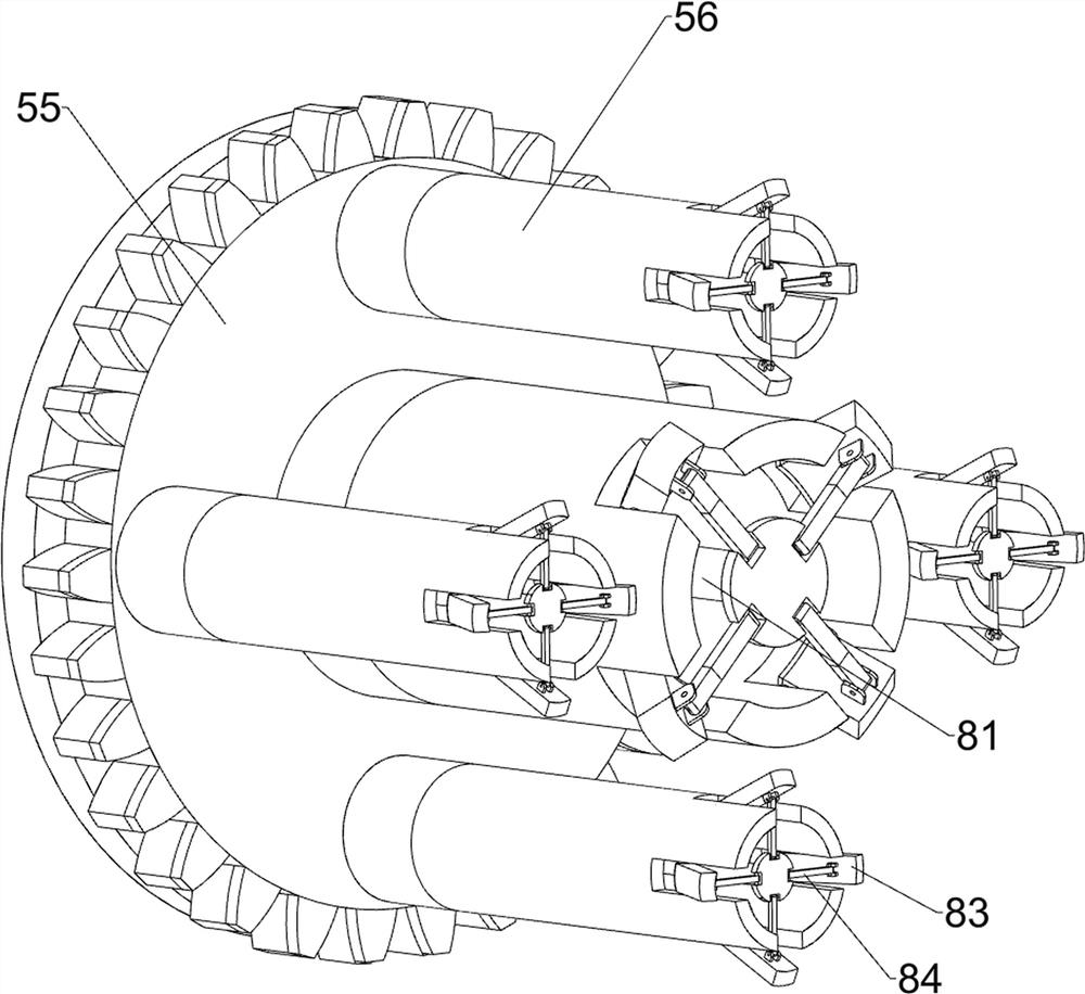
[0038] On the basis of Example 2, such as Figure 4 with Figure 5 As shown, a clamping assembly 8 is also included. The clamping assembly 8 includes a second carriage 81, a second compression spring 82, a block 83 and a second connecting rod 84, and the inner sides of the toothed discs 55 on both sides are slidably connected. There is a second slide frame 81, and a second compression spring 82 is connected between the second slide frame 81 on both sides and the tooth discs 55 on both sides, and the outside of the positioning shaft 56 on both sides is connected with a block 83 in a rotational manner. The inner sides of the clamping blocks 83 are rotatably connected with second connecting rods 84, and the second connecting rods 84 on both sides are rotatably connected to the second sliding frames 81 on both sides.

[0039] When it is necessary to carry out the wear test to the automobile tires, first the tires are manually placed on the positioning shafts 56 on both sides, and...


PUM


Abstract

The invention relates to a test device, in particular to an automobile tire wear test comparison device. The technical problem to be solved by the invention is to provide the automobile tire wear test comparison device which has the advantages that the stress of a tire is the same in a polishing process, the surface wear of the tire does not need to be visually inspected manually, and the test is accurate, error-free and high-efficiency. In order to solve the technical problem, the invention provides the automobile tire wear test comparison device which comprises: a base connected with a supporting plate; a fixing plate which is connected to the base; a fixing frame which is connected to the supporting plate; a rotating assembly which is connected to the base; and a friction assembly which is rotationally connected to the fixing plate. Through the rotating assembly and the friction assembly, a tire is rotated and polished, a wear test is carried out on the tire, through the braking assembly, it is more convenient to see the states of the tires on the two sides when a worker wants to stop, and rotation of a fluted disc can be manually controlled.

Description

technical field [0001] The invention relates to a test device, in particular to an automobile tire wear test comparison device. Background technique [0002] Car tires are one of the important parts of the car. They are in direct contact with the road surface, and together with the car suspension to ease the impact of the car when driving, to ensure that the car has good ride comfort and ride comfort, and to ensure that the wheels and the road have a good Good adhesion can improve the traction, braking and passability of the car; bearing the weight of the car, the important role played by tires on the car has attracted more and more attention. [0003] At present, people usually carry out wear test on tires by manually fixing two tires on two rotating rods with the same rotating speed, and then wear the two rotating tires by manually holding abrasive paper, and finally manually test the two tires. Visual observation is used for comparison. This test requires manual wear of ...

Claims


Application Information

Patent Timeline
IPC IPC(8): G01N3/56G01N3/02G01N3/04G01N3/06G01M17/02
CPCG01M17/02G01M17/021G01N3/02G01N3/04G01N3/062G01N3/56G01N2203/0005G01N2203/005G01N2203/0605G01N2203/0682
Inventor 黄志传
Owner 黄志传
Why Eureka
Try Eureka