Electro-hydraulic integrated swashplate and plunger type hydraulic transformer

A hydraulic transformer and plunger technology, applied in the direction of fluid pressure converters, mechanical equipment, etc., can solve the problems of unstable output pressure, large volume and weight of the transformer, and small transformation range, so as to improve work efficiency and shorten the overall Length, the effect of improving swing accuracy

Inactive Publication Date: 2017-12-12
XUZHOU UNIV OF TECH
View PDF6 Cites 6 Cited by
  • Summary
  • Abstract
  • Description
  • Claims
  • Application Information

AI Technical Summary

Problems solved by technology

This type of transformer has a large volume and weight, requires a relatively large adjustment force, high cost, and low efficiency.
[0004] The new integrated hydraulic transformer integrates the functions of the hydraulic motor and the hydraulic pump, and uses the hydraulic motor to drive the rotation of the valve plate of the plunger pump. Three waist-shaped distribution grooves are processed on the valve plate, but because the valve plate is rotating, During the rotation process, the flow area between the distribution plate and the rear end cover gradually decreases, and the throttling effect between the rear end cover and the distribution plate increases, which will cause a large energy throttling loss and reduce the efficiency of the hydraulic transformer; The inertia of the plate and the cylinder is small, and the anti-interference ability is poor. Therefore, a slight change of the valve plate will change the balance of the torque of the cylinder and the rotation speed of the transformer, and then change the flow of the hydraulic transformer, resulting in unstable output pressure; The rotation angle of the distribution plate around the central axis of the cylinder is used to realize the oil flow in and out of the three waist distribution grooves of the transformer, thereby adjusting the rotation speed of the cylinder and the transformation ratio of the hydraulic transformer. In order to ensure the effective flow area, only further The rotation angle range is limited, so the voltage transformation range is small, and the transformation ratio control accuracy is low; and the existing new hydraulic transformer still has the problem of large control structure and unable to actively control the flow

Method used


Image

  • Electro-hydraulic integrated swashplate and plunger type hydraulic transformer
  • Electro-hydraulic integrated swashplate and plunger type hydraulic transformer
  • Electro-hydraulic integrated swashplate and plunger type hydraulic transformer

Examples


Embodiment Construction

[0024] The present invention will be further described below in conjunction with accompanying drawing.

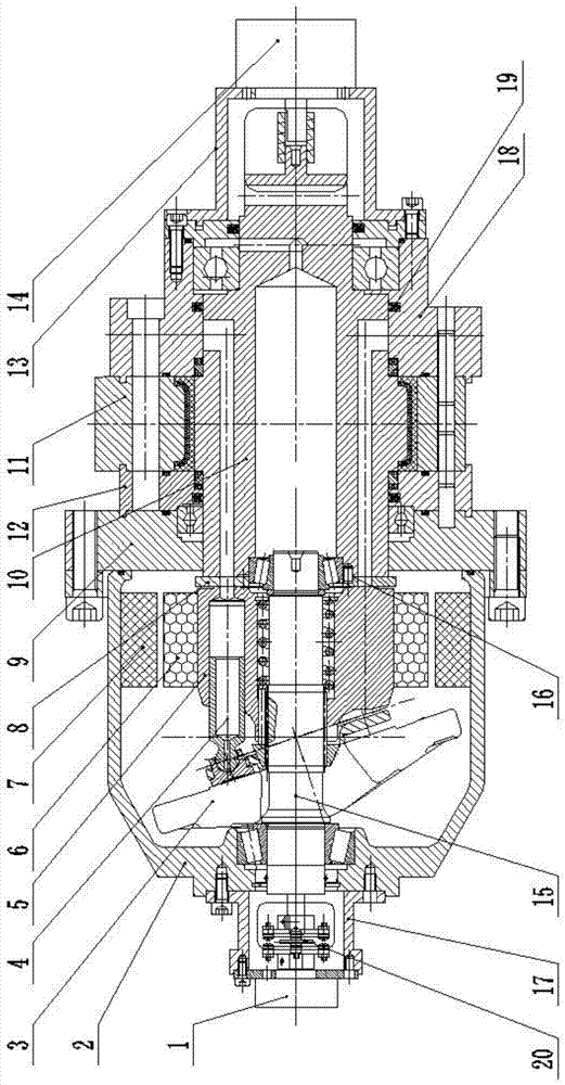
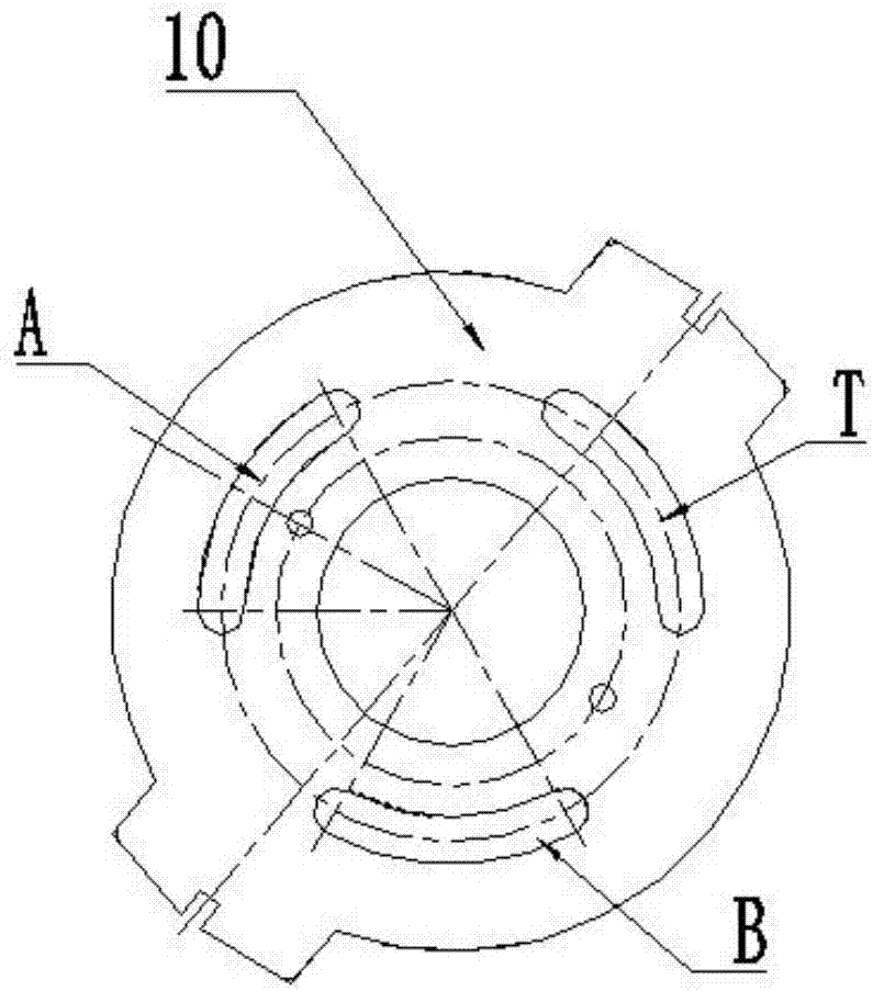
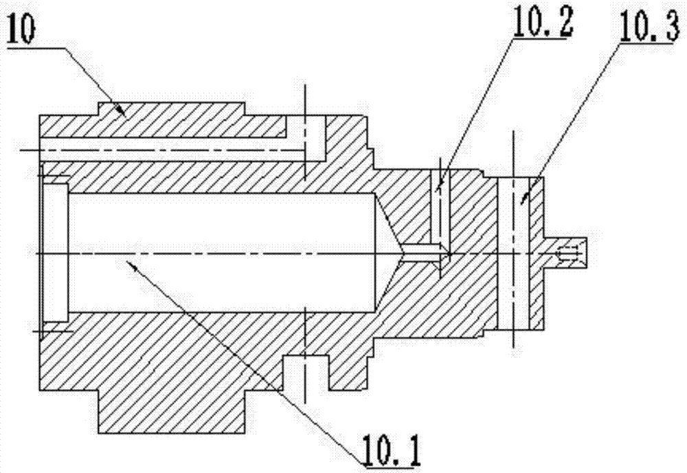
[0025] Such as Figures 1 to 4 As shown, an electro-hydraulic integrated swash plate plunger type hydraulic transformer includes a hydraulic transformer housing 2, a cylinder body 5, a flow plate 8, a plunger 4 and a swash plate 3, and the cylinder body 5 is installed on the output shaft 15 through a spline , the distribution plate 8 is set at one end of the cylinder body 5 and is in sealing contact with the cylinder body 5, the swash plate 3 is set at the other end of the cylinder body 5 and installed on the hydraulic transformer shell 2, there are several plunger cavities in the cylinder body 5, and the plunger 4 is installed in the plunger cavity and one end is in sliding contact with the swash plate 3, and also includes the rear end cover 9, the swing hydraulic motor 11 and the distribution shaft 10, the distribution shaft 10 is the swing shaft of the swing hydraulic mo...


PUM


Abstract

The invention discloses an electro-hydraulic integrated swashplate and plunger type hydraulic transformer. The electro-hydraulic integrated swashplate and plunger type hydraulic transformer comprises a hydraulic transformer housing, a cylinder block, a valve plate, a plunger, a swashplate, a rear end cover, a swinging hydraulic motor and a flow distribution shaft. The flow distribution shaft serves as a swinging shaft of the swinging hydraulic motor. The flow distribution shaft is connected with the valve plate through a pin shaft and sealing is achieved through contact end faces. Three kidney-shaped flow distribution grooves are formed in the valve plate. Flow distribution grooves matched with the three flow distribution grooves in the valve plate in size are formed in the flow distribution shaft. By the adoption of the electro-hydraulic integrated swashplate and plunger type hydraulic transformer, the swinging hydraulic motor is integrally mounted in a flow distribution shell of the hydraulic transformer, and three oil outlets of the flow distribution shaft are uniformly distributed in the positions with the same axial size of the flow distribution shaft, and the whole length of the hydraulic transformer is reduced effectively; and the valve plate is connected with the flow distribution shaft, the transformer ratio of the hydraulic transformer is increased, the pressure transformation range of the hydraulic transformer is broadened, and the throttling loss is avoided.

Description

technical field [0001] The invention relates to a hydraulic transformer, in particular to an electro-hydraulic integrated swash plate plunger type hydraulic transformer, which belongs to the technical field of hydraulic control equipment. Background technique [0002] The hydraulic transformer is a hydraulic equipment that uses the secondary regulation technology of the hydraulic constant voltage network to transmit the energy of the constant voltage network with high efficiency and variable pressure. It has the advantages of low cost, excellent control performance, and stable operation. [0003] The traditional hydraulic transformer directly connects the hydraulic motor and the hydraulic pump coaxially. By adjusting the displacement of the hydraulic motor, the input pressure is changed to the pressure required by the load, so as to realize the pressure change. This type of transformer has a large volume and weight, requires relatively large adjustment force, high cost, and ...

Claims


Application Information

Patent Timeline
Patent Type & Authority Applications(China)
IPC IPC(8): F15B3/00
CPCF15B3/00
Inventor 刘成强黄传辉李志何绍华于萍刘磊
Owner XUZHOU UNIV OF TECH
Why Eureka
Try Eureka