Supercharge Your Innovation With Domain-Expert AI Agents!

Vocal cavity structure and sound box

A technology of acoustic cavity and recessed structure, applied in sensor parts, sensors, electrical components, etc., can solve the problem of not being able to meet the needs of sound production

Active Publication Date: 2021-06-08
GEER TECH CO LTD
View PDF14 Cites 1 Cited by
  • Summary
  • Abstract
  • Description
  • Claims
  • Application Information

AI Technical Summary

Problems solved by technology

[0003] The existing sound cavity design is divided into a front cavity and a rear cavity by a speaker. The front cavity and the rear cavity form a fixed cavity after the speaker is installed. The sound effect of the speaker is uniform and cannot adapt to different sound requirements.

Method used


Image

  • Vocal cavity structure and sound box
  • Vocal cavity structure and sound box
  • Vocal cavity structure and sound box

Examples


Embodiment Construction

[0037] Various exemplary embodiments of the present invention will now be described in detail with reference to the accompanying drawings. It should be noted that the relative arrangements of components and steps, numerical expressions and numerical values ​​set forth in these embodiments do not limit the scope of the present invention unless specifically stated otherwise.

[0038] The following description of at least one exemplary embodiment is merely illustrative in nature and in no way taken as limiting the invention, its application or uses.

[0039] Techniques, methods and devices known to those of ordinary skill in the relevant art may not be discussed in detail, but where appropriate, such techniques, methods and devices should be considered part of the description.

[0040] In all examples shown and discussed herein, any specific values ​​should be construed as exemplary only, and not as limitations. Therefore, other instances of the exemplary embodiment may have dif...


PUM


Abstract

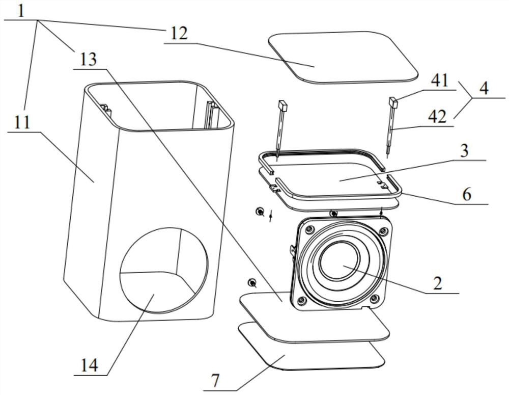
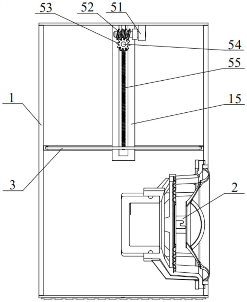
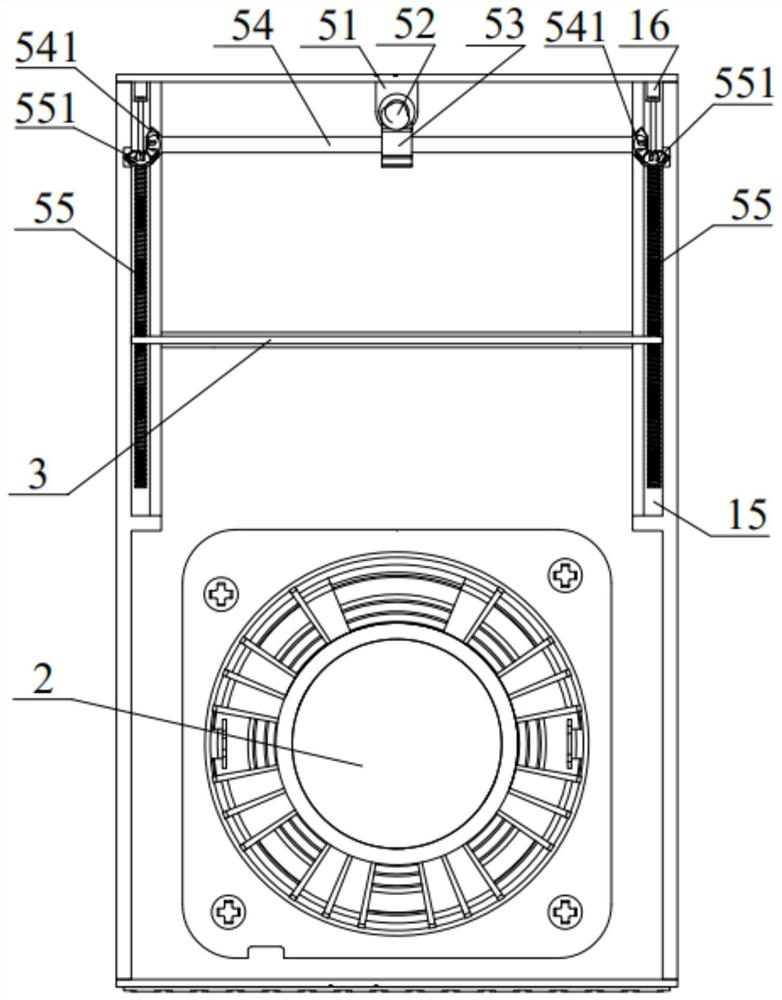
The invention discloses a vocal cavity structure and a sound box. The vocal cavity structure comprises a vocal cavity body, a sound insulation plate and a driving assembly, wherein the vocal cavity body is provided with a mounting hole, and the mounting hole is used for mounting a loudspeaker; the sound insulation plate is arranged in the vocal cavity body, and the sound insulation plate divides the vocal cavity body into a first cavity and a second cavity which are sealed and isolated; the driving assembly is used for driving the sound insulation plate to move so as to adjust the size of the first cavity and the size of the second cavity; and the mounting hole communicates with the second cavity. According to one embodiment of the invention, the driving assembly drives the sound insulation plate to move, thereby changing the size of the second cavity, enabling the size of the rear sound cavity of the loudspeaker to be adjustable, and being capable of meeting different sound production requirements.

Description

technical field [0001] The invention relates to the technical field of audio equipment, and more specifically, to an acoustic cavity structure and a sound box. Background technique [0002] With the development of electronic products and the increase of users' demand for electronic products, the performance requirements of electronic products are becoming more and more stringent. The rear cavity of the current speaker affects the size of the entire product. [0003] The existing sound cavity design is divided into a front cavity and a rear cavity by a speaker. The front cavity and the rear cavity form a fixed cavity after the speaker is installed. The sound effect of the speaker is uniform and cannot adapt to different sound requirements. [0004] Therefore, a new technical solution needs to be provided to solve the above technical problems. Contents of the invention [0005] An object of the present invention is to provide a new technical solution for the acoustic cavit...

Claims


Application Information

Patent Timeline
Patent Type & Authority Applications(China)
IPC IPC(8): H04R1/02H04R1/28
CPCH04R1/02H04R1/2811
Inventor 高爱丽
Owner GEER TECH CO LTD
Features
  • R&D
  • Intellectual Property
  • Life Sciences
  • Materials
  • Tech Scout
  • Unparalleled Data Quality
  • Higher Quality Content
  • 60% Fewer Hallucinations
Learn More