A tilting mechanism, carriage and railway self-overturning vehicle

A technology of tipping mechanism and car box, which is applied to railway car body parts, dump trucks, transport passenger cars, etc., can solve the problems of inflexible dumping of goods and classification, inconsistent turning angles, and reduced unloading efficiency, so as to save transportation capacity and improve the efficiency of unloading. The effect of unloading rate and improving unloading efficiency

Active Publication Date: 2022-05-13
CRRC SHANDONG CO LTD +1
View PDF22 Cites 0 Cited by
  • Summary
  • Abstract
  • Description
  • Claims
  • Application Information

AI Technical Summary

Problems solved by technology

[0004] At present, the existing self-dumping vehicles generally use the side door to turn from top to bottom, and with the inclination of the carriage, the side door and the carriage floor form a slideway surface for dumping goods. The angles are inconsistent, and the side door can only be fully opened when the carriage is turned over significantly, which reduces the unloading efficiency, and because the side door acts as the unloading floor for a long time, it is also prone to deformation and damage
In addition, the current self-dumping trucks are not flexible in carrying goods and sorting and dumping, and there is a waste of transport capacity

Method used


Image

  • A tilting mechanism, carriage and railway self-overturning vehicle
  • A tilting mechanism, carriage and railway self-overturning vehicle
  • A tilting mechanism, carriage and railway self-overturning vehicle

Examples


Embodiment 2

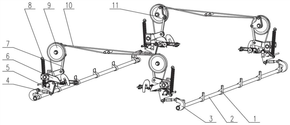
[0051] In this embodiment, a kind of railway self-rolling car box is provided, and the car box includes a box structure, side door components 15 are arranged on both sides of the box structure, end door components 13 are arranged at the end of the box structure, the side door components are fixed by steel beams at the top, and It can be opened and closed but the rotation angle is limited to prevent the side door from being washed away by the cargo during the tipping process.

[0052] The side door can be self-limited to limit the turning range.

[0053] The end door is composed of a tilting mechanism installation seat plate for fixing the tilting mechanism as described in Embodiment 1.

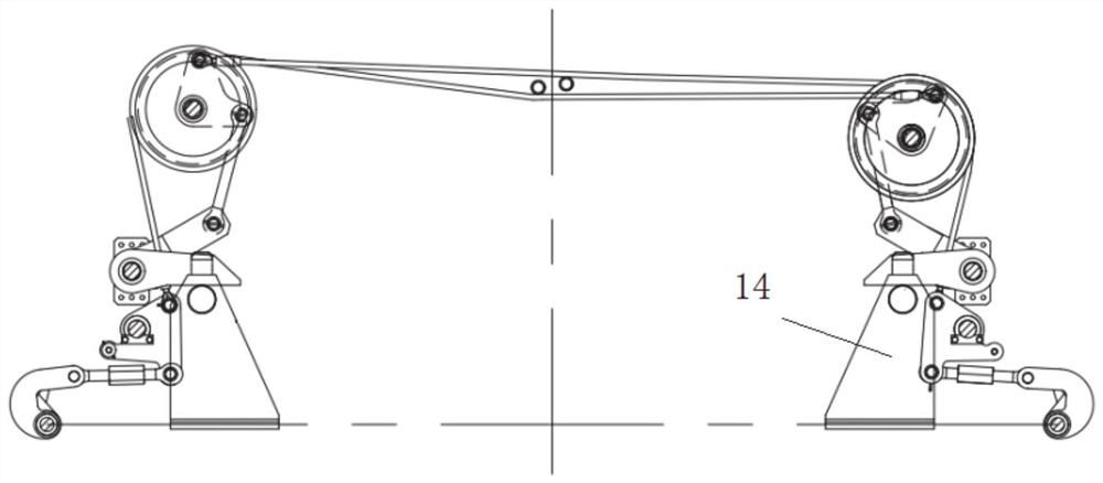
[0054] Lock seats 14 are arranged on both sides of the end door composition, and lock shafts are arranged on the lock seats. When the carriage does not tip over, the lock bar formed by the lock door pressing bar overlaps and is compressed on the lock shaft, and the lock seat and the lock door ...

Embodiment 3

[0058] In this embodiment, a railway self-dumping car is proposed, which includes a car body, and the car body is provided with a car box as described in the second embodiment.

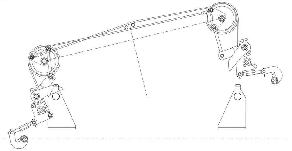
[0059] In this embodiment, each self-tipping vehicle is provided with two sets of carriages, and each set of carriages is equipped with the same tilting mechanism that operates independently, so that the tilting operation can be performed asynchronously.

[0060] The car body comprises an underframe, the carriage is arranged on the top of the underframe, and the outside of the side beam of the underframe is provided with a shroud 16, which is correspondingly arranged below the side door, and the shroud is arranged obliquely, that is, the shroud is arranged with the vertical direction. With a fixed angle, the shroud is used to dump goods when the vehicle is in overturning operation, improving the discharge rate of fine ore or slag, and preventing it from entering and accumulating in the lower chassis an...


PUM


Abstract

The invention discloses a tipping mechanism, a carriage and a railway self-overturning car, which comprise two oppositely arranged rotating shafts, both ends of which are connected to a door locking linkage mechanism, and the door locking linkage mechanisms at opposite ends of the two rotating shafts are connected; each lock The door link mechanism includes a first rotary lever and a second rotary lever, the first rotary lever is connected to the door opening pull rod, and the door opening pull rod is connected to the rotating shaft; among the two connected door lock link mechanisms, one of the door lock link mechanisms The first rotary lever is connected with the second rotary mechanism of another door locking linkage mechanism through a wire rope.

Description

technical field [0001] The invention belongs to the technical field of railway wagons, and in particular relates to a tipping mechanism, a carriage and a railway self-overturning wagon. Background technique [0002] The statements herein merely provide background information related to the present invention and do not necessarily constitute prior art. [0003] Railway transportation is a transportation mode with large transportation volume, fast speed and low cost. At present, there are many types of railway self-dumping vehicles. Bulk cargo such as ore, stripped rock, gravel, coal, construction materials, etc. [0004] At present, the existing self-dumping vehicles generally use the side door to turn from top to bottom, and with the inclination of the carriage, the side door and the carriage floor form a slideway surface for dumping goods. The angles are inconsistent, and the side door can only be fully opened when the carriage is turned over significantly, which reduces ...

Claims


Application Information

Patent Timeline
Patent Type & Authority Patents(China)
IPC IPC(8): B61D9/02B61D9/06
CPCB61D9/02B61D9/06
Inventor 翟凤宇王永兵周烨孟凡臣张龙
Owner CRRC SHANDONG CO LTD
Why Eureka
Try Eureka