Foundation pile for building

A technology for construction and foundation piles, which is applied in construction, sheet pile walls, foundation structure engineering, etc., can solve the problems of pile heads being fragile, and achieve the effect of increasing lateral stability, increasing stability, and increasing load

Inactive Publication Date: 2021-06-11
李良容
View PDF0 Cites 1 Cited by
  • Summary
  • Abstract
  • Description
  • Claims
  • Application Information

AI Technical Summary

Problems solved by technology

[0005] Aiming at the deficiencies of the prior art, the present invention provides a foundation pile for construction, which solves the problem that the pile head is easily broken

Method used


Image

  • Foundation pile for building
  • Foundation pile for building
  • Foundation pile for building

Examples


Embodiment 1

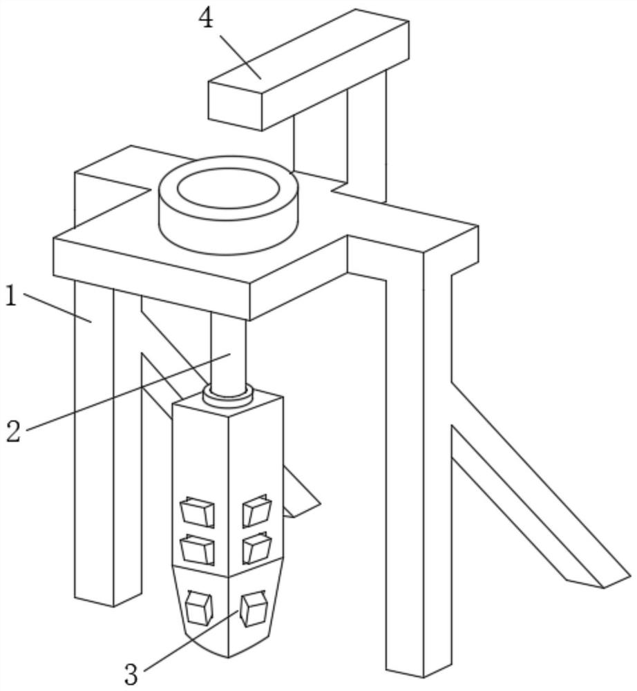
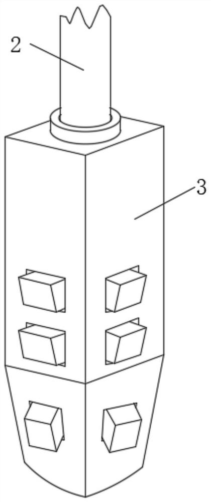
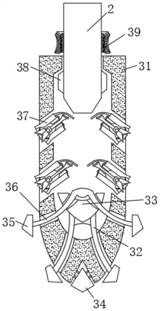
[0033] like Figure 1-4 As shown, the present invention provides a technical solution: a foundation pile for construction, including a pile driving frame 1, a tamper 4 is fixedly connected to the top of the pile driving frame 1, and a pile body is sleeved on the upper surface of the pile driving frame 1 2. The bottom of the pile body 2 is movably connected with a pile head device 3, and the pile head device 3 includes a shifting block 38 and a chuck device 39, and the outer surface of the bottom of the pile body 2 is sleeved with a pile head shell 31, The outer surface of the pile body 2 is fixedly connected with a chuck device 39 and a shifting block 38 respectively, and the shifting block 38 is arranged at the inner chamber of the pile head case 31 and is adapted thereto, and the opening of the pile head case 31 inner wall A lateral pressure device 37 is sleeved at the center of the pile, a protective block 34 is fixedly connected to the bottom of the pile head shell 31 , an...

Embodiment 2

[0037] like Figure 5-7 As shown, on the basis of Embodiment 1, the present invention provides a technical solution: the side pressure device 37 includes a side pressure shell 371, and the outer surface of the side pressure shell 371 is sleeved on the outer surface of the pile head shell 31. At the opening, the top of the left side of the side pressure shell 371 is fixedly connected with a pressure plate 372, and the inner wall of the right side of the side pressure shell 371 is fixedly connected with an anti-seepage ring 374, and the inside of the anti-seepage ring 374 is sleeved with Pressing rod 373 , the top of the pressing rod 373 fits with the pressing plate 372 .

[0038] The bottom of the pressure rod 373 is fixedly connected with a bifurcated rod 375, and the end of the bifurcated rod 375 away from the pressure rod 373 is fixedly connected with a catch device 376, and the bottom of the inner wall of the side pressure shell 371 is fixedly connected with an anti-seepage...


PUM


Abstract

The invention discloses a foundation pile for a building. The foundation pile comprises a pile driving frame, wherein the top of the pile driving frame is fixedly connected with a rammer; the upper surface of the pile driving frame is in sleeve connection with a pile body; the bottom of the pile body is movably connected with a pile head device; the pile head device comprises a pulling block and a chuck device; the outer surface of the bottom of the pile body is in sleeve connection with a pile head shell; the outer surface of the pile body is fixedly connected with the chuck device and the pulling block respectively; the pulling block is arranged in an inner cavity of the pile head shell and is adaptive to the inner cavity; a side pressing device is in sleeve connection with an opening of an inner wall of the pile head shell; the bottom end of the pile head shell is fixedly connected with a protection block; and a pressing block is arranged at the bottom of the inner cavity of the pile head shell. The invention relates to the technical field of buildings. According to the foundation pile for the building, the pile body is hit through the rammer so that the foundation pile for the building is pressed to move downward to enter soil; the pile head device is arranged at the bottom of the pile body so that the effect of protecting the bottom of the pile body in an underground high-pressure environment is realized.

Description

technical field [0001] The invention relates to the technical field of construction, in particular to a foundation pile for construction. Background technique [0002] Pile foundation is a deep foundation that connects the tops of several piles into a whole through caps to bear dynamic and static loads together. Pile is a vertical or inclined foundation component set in the soil, and its function is to pass through the weak high compression The soil layer or water transfers the load borne by the pile to the harder, denser or less compressible foundation rock layer. We usually refer to the piles in the pile foundation as foundation piles. [0003] When traditional piles are rammed into the foundation, multiple rammings make the piles pass through the soft soil layer and enter the hard rock layer. However, because the piles are underground when they are rammed, and the depth of the rock layer is unknown, it is not clear when the piles will touch the rock layer. , resulting in...

Claims


Application Information

Patent Timeline
Patent Type & Authority Applications(China)
IPC IPC(8): E02D7/02E02D27/12
CPCE02D7/02E02D27/12
Inventor 李良容
Owner 李良容
Why Eureka
Try Eureka