Drilling wall-protecting slurry circulating device and method for engineering investigation in underground water-rich area

A technology of engineering survey and circulation device, which is applied in earth-moving drilling, wellbore/well components, flushing wellbore, etc., can solve the problems of reducing engineering exploration efficiency, insufficient mud water viscosity, unstable wall mud, etc. Improve exploration efficiency, improve mixing effect, and save the effect of the process of rebuilding the mud circulation device

Active Publication Date: 2021-06-11
安徽建材地质工程勘察院有限公司
View PDF17 Cites 1 Cited by
  • Summary
  • Abstract
  • Description
  • Claims
  • Application Information

AI Technical Summary

Problems solved by technology

[0002]Our country is vast and abundant, and there is abundant groundwater under the vast land. In some areas in the southwest, the groundwater resources are particularly rich. However, when carrying out engineering surveys in areas with abundant groundwater, Drilling is required. During the drilling process, because the groundwater is too rich and the viscosity of the mud water is not enough, the effect of the wall protection cannot be achieved, and the hole wall is likely to collapse. Therefore, it is necessary to use a mud circulation device during the drilling process. , improve the viscosity of mud water, and further ensure the progress of exploration;
[0003]Currently, the conventional mud circulation is only carried out between the mud pool and the drilling, and the mud treatment is not effective enough, resulting in poor hole quality and unstable wall mud. At the same time, the efficiency of the entire mud circulation device is low. As the exploration location moves, it needs to be rebuilt, which further consumes a lot of manpower and material resources, reducing the efficiency of the entire engineering exploration.

Method used


Image

  • Drilling wall-protecting slurry circulating device and method for engineering investigation in underground water-rich area
  • Drilling wall-protecting slurry circulating device and method for engineering investigation in underground water-rich area
  • Drilling wall-protecting slurry circulating device and method for engineering investigation in underground water-rich area

Examples


Embodiment Construction

[0032] The following will clearly and completely describe the technical solutions in the embodiments of the present invention with reference to the accompanying drawings in the embodiments of the present invention. Obviously, the described embodiments are only some, not all, embodiments of the present invention. Based on the embodiments of the present invention, all other embodiments obtained by persons of ordinary skill in the art without creative efforts fall within the protection scope of the present invention.

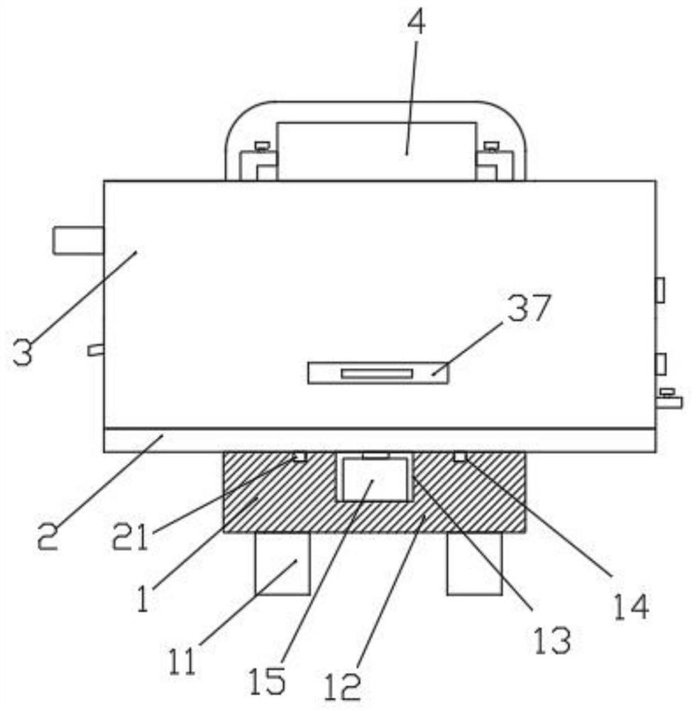
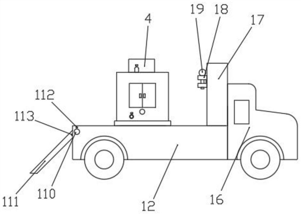
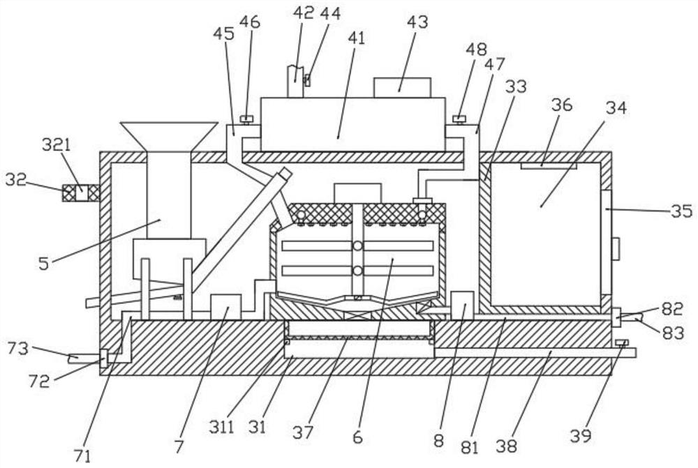
[0033] see Figure 1-5 As shown, the drilling wall mud circulation device for engineering surveys in areas with abundant groundwater includes a transport vehicle 1, a support plate 2, a working box 3, a cleaning mechanism 4, a conveying mechanism 5, and a stirring mechanism 6. A support plate is installed on the top of the transport vehicle 1 2. A working box 3 is arranged on the top of the support plate 2, a conveying mechanism 5 is arranged on one side of the inn...


PUM


Abstract

The invention discloses a drilling wall-protecting slurry circulating device and method for engineering investigation in an underground water-rich area. The drilling wall-protecting slurry circulating device comprises a transport cart, a support plate, a working box, a cleaning mechanism, a conveying mechanism and a mixing mechanism, wherein the support plate is installed on the top of the transport cart, the working box is arranged on the top of the support plate, the conveying mechanism is arranged on one side of the interior of the working box, the mixing mechanism is arranged in the middle of the interior of the working box, and the cleaning mechanism is installed in the middle of the top of the working box. After the structure is adopted, reverse circulation can be performed on drilling wall-protecting slurry, the viscosity of the slurry is further increased, the inner wall of a drill hole is preferably protected, collapse is prevented, and additionally, the device is arranged on the transport cart, so that the whole device can be further conveniently turned over and used.

Description

technical field [0001] The invention relates to the technical field of mud circulation devices, in particular to a drilling wall mud circulation device and method for engineering surveys in areas with abundant groundwater. Background technique [0002] Our country is vast and abundant, and there is abundant groundwater under the vast land. In some areas in the southwest, the groundwater resources are particularly rich. However, when carrying out engineering surveys in areas with rich groundwater, it is necessary to drill holes. During the drilling process, due to the abundance of groundwater , the viscosity of the mud water is not enough to achieve the effect of the retaining wall, and it is easy to cause the hole wall to collapse. Therefore, it is necessary to use a mud circulation device during the drilling process to improve the viscosity of the mud water and further ensure the progress of exploration; [0003] At present, the conventional mud circulation is only carried ...

Claims


Application Information

Patent Timeline
Patent Type & Authority Applications(China)
IPC IPC(8): E21B21/06
CPCE21B21/062E21B21/065
Inventor 尤炎炎
Owner 安徽建材地质工程勘察院有限公司
Why Eureka
Try Eureka