
Dielectric filter

A dielectric filter and resonator technology, applied in the field of filters, can solve the problems of affecting the filter suppression performance, large design limitations, limited harmonic frequency adjustment, etc., to improve design flexibility and adaptability, improve low frequency Suppressing performance, improving the effect of low frequency harmonics

Pending Publication Date: 2021-06-11
MOBILE ANTENNA TECH SHENZHEN +5
View PDF1 Cites 3 Cited by
  • Summary
  • Abstract
  • Description
  • Claims
  • Application Information

AI Technical Summary

Problems solved by technology

The structure of capacitive coupling is simple and easy to implement in this way, but because the resonator working in TE102 mode still has TE101 mode and the resonant frequency of TE101 mode is lower than that of TE102 mode, the passband of the ceramic dielectric filter will be low in frequency. Generate spurious harmonics, which affect the rejection performance of the filter at low frequencies
Especially when the ceramic dielectric filter has at least two resonators working in the TE102 mode, the respective TE101 modes of these resonators will generate at least two spurious harmonics at the low frequency of the passband, and the harmonics are superimposed on each other when their frequencies are close. Severely affects low-frequency rejection performance
Although the resonant frequency interval of the two modes can be adjusted to a certain extent by adjusting the spacing of the double blind holes of the resonator, the change of the spacing not only affects the frequencies of the two modes at the same time, but also changes the adjacent coupling amount, so the design is limited Larger, the amount of adjustment to the harmonic frequency is also very limited
[0004] In summary, there are obviously inconveniences and defects in the actual use of the existing technology, so it is necessary to improve

Method used


Image

  • Dielectric filter
  • Dielectric filter
  • Dielectric filter

Examples


Embodiment Construction

[0047]In order to make the object, technical solution and advantages of the present invention clearer, the present invention will be further described in detail below in conjunction with the accompanying drawings and embodiments. It should be understood that the specific embodiments described here are only used to explain the present invention, not to limit the present invention.

[0048] It should be noted that references in this specification to "one embodiment", "embodiment", "example embodiment" and the like mean that the described embodiment may include specific features, structures or characteristics, but not every Embodiments must include those specific features, structures or characteristics. Furthermore, such expressions are not referring to the same embodiment. Further, when specific features, structures or characteristics are described in conjunction with an embodiment, whether or not there is an explicit description, it has been indicated that it is within the kno...


PUM


Abstract

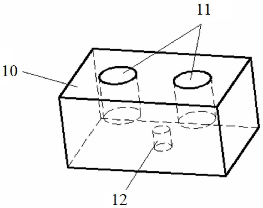
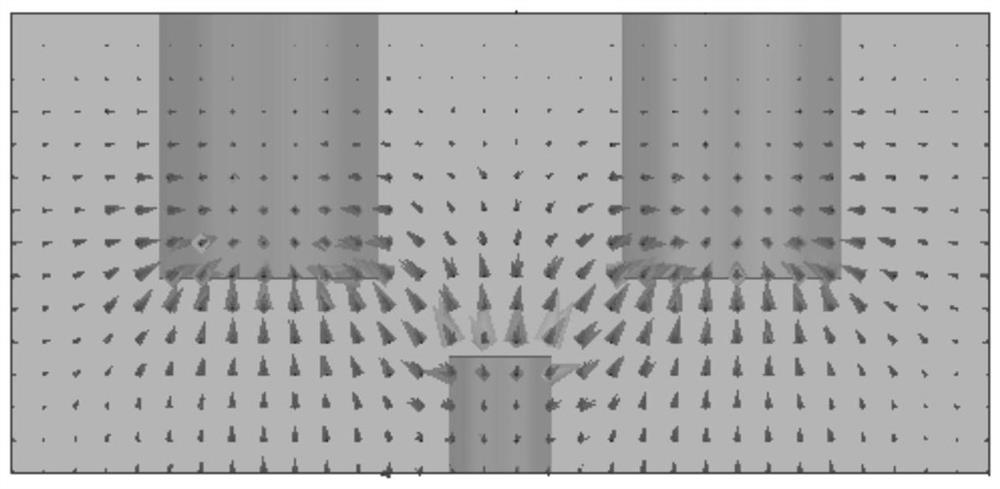
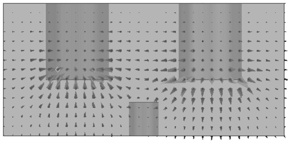
The invention provides a dielectric filter. The dielectric filter comprises at least one first resonator working in a TE102 mode and at least one second resonator working in a TE101 mode, wherein the top surface and the bottom surface of the first resonator respectively comprise a top surface center and a bottom surface center which are symmetrical; a pair of first tuning blind holes are symmetrically formed in the top surface of the first resonator about the center of the top surface; a bottom blind hole is formed in the center of the bottom surface of the first resonator; and / or the first resonator has a through hole penetrating through the top surface and the bottom surface, and the through hole is located on a perpendicular bisector corresponding to a connecting line of the pair of first tuning blind holes. Therefore, the frequency of loading the TE101 mode can be reduced or increased under the condition that the influence on the frequency of loading the TE102 mode is small, the low-frequency suppression performance can be greatly improved, the structure is simple, implementation is easy, and the design flexibility and adaptability of the dielectric filter are further improved.

Description

technical field [0001] The invention relates to the technical field of filters, in particular to a dielectric filter. Background technique [0002] Filter is an indispensable frequency selective device in wireless communication. Dielectric filters based on ceramics have more and more application prospects due to their compact size and excellent performance. [0003] Chinese invention patent CN201980001851.9 discloses a ceramic dielectric filter. The capacitive coupling method of the ceramic dielectric filter is realized by using a double blind hole structure to load the TE102 mode. The structure of capacitive coupling is simple and easy to implement in this way, but because the resonator working in TE102 mode still has TE101 mode and the resonant frequency of TE101 mode is lower than that of TE102 mode, the passband of the ceramic dielectric filter will be low in frequency. Generate spurious harmonics, thereby affecting the suppression performance of the filter at low frequ...

Claims


Application Information

Patent Timeline
Patent Type & Authority Applications(China)
IPC IPC(8): H01P1/20
CPCH01P1/2002
Inventor 刘磊王津孟银李军杰郝勖加
Owner MOBILE ANTENNA TECH SHENZHEN
Learn More