
Film cleaning equipment for film production

A technology for cleaning equipment and films, which can be applied to cleaning methods using tools, cleaning methods using gas flow, cleaning methods and utensils, etc., and can solve problems such as being difficult to fall off and being caught on cleaning rollers.

Inactive Publication Date: 2021-06-15
广州市灵升商贸有限公司
View PDF8 Cites 3 Cited by
  • Summary
  • Abstract
  • Description
  • Claims
  • Application Information

AI Technical Summary

Problems solved by technology

[0003] Since the film cleaning machine sandwiches the film between two cleaning rollers for cleaning, and the film that is prone to static electricity on the surface is similar to the plastic wrap, it is easy to adhere to the surface of the cleaning roller after passing through the two cleaning rollers, and it is difficult to fall off. , resulting in being drawn into the cleaning roller by the cleaning roller

Method used


Image

  • Film cleaning equipment for film production
  • Film cleaning equipment for film production
  • Film cleaning equipment for film production

Examples


Embodiment 1

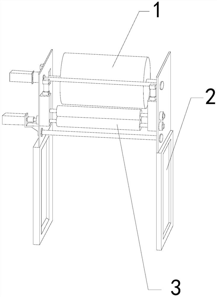
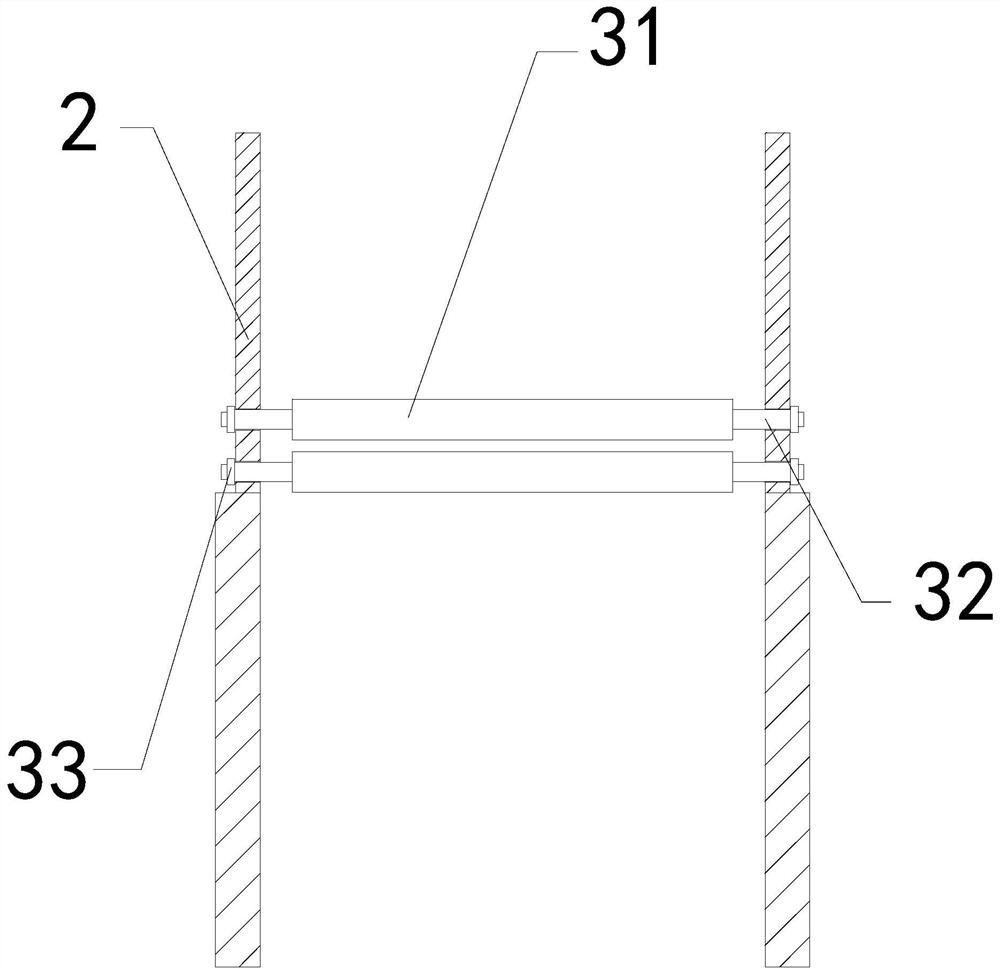
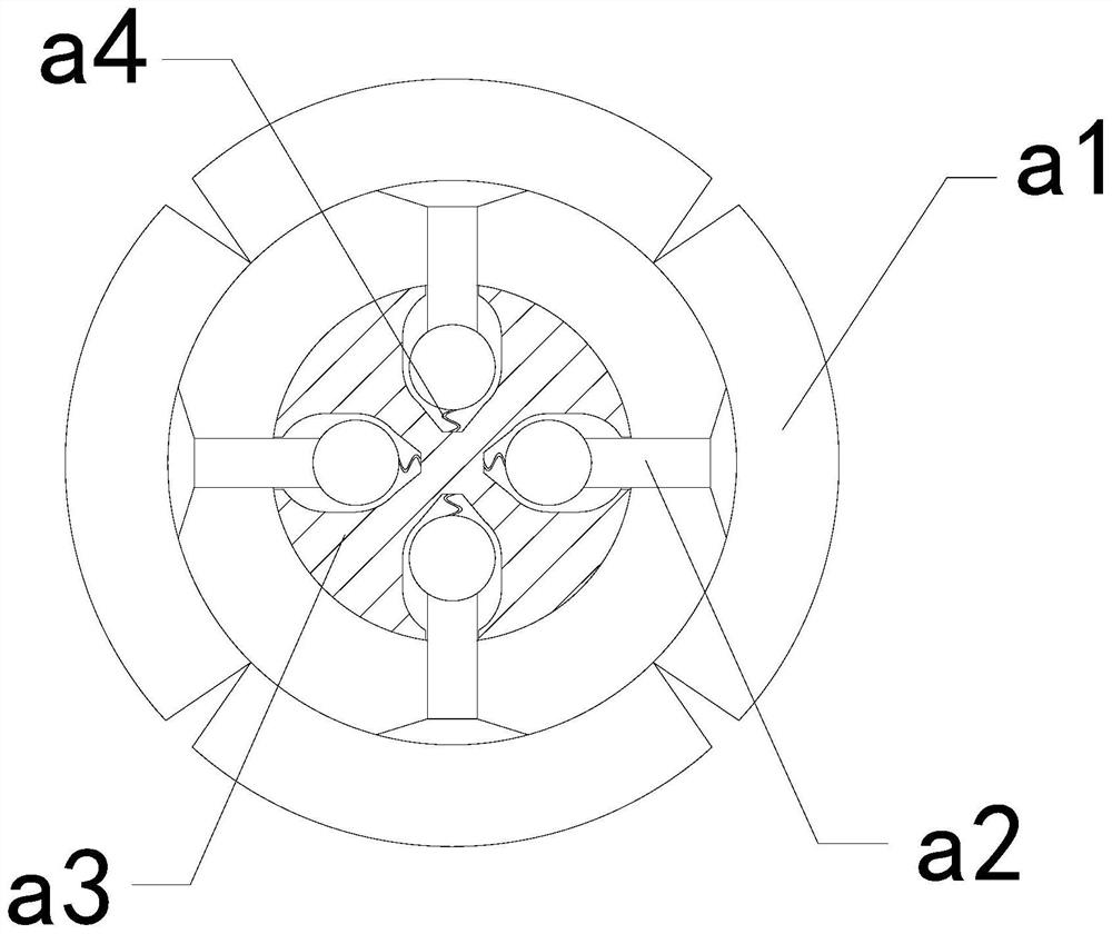
[0026] For example figure 1 -example Figure 5 Shown:

[0027] The invention provides a film cleaning device for film production, the structure of which includes a film collecting roller 1, a support frame 2, and a cleaning mechanism 3, the film collecting roller 1 is movable and engaged with two support frames 2, and the cleaning mechanism 3 is installed between the inner sides of the two supporting frames 2; the cleaning mechanism 3 includes a cleaning roller 31, a rotating shaft 32, and a fixed head 33, the cleaning roller 31 and the rotating shaft 32 are an integrated structure, and the fixed head 33 is embedded on the outer side of the rotating shaft 32.

[0028] Wherein, the cleaning roller 31 includes an outer pushing plate a1, a linkage rod a2, a middle solid block a3, and a pull-back bar a4. The block a3 is movable and engaged, the pull-back strip a4 is fixed between the inner side of the linkage rod a2 and the inner wall of the middle solid block a3, and there are...

Embodiment 2

[0034] For example Figure 6 -example Figure 8 Shown:

[0035] Wherein, the air-permeable cavity a14 includes a middle swing plate c1, an outer frame c2, a pullback bar c3, a middle strut c4, and an upward extension ball c5, and the middle swing plate c1 is hingedly connected to the upper end of the middle strut c4. The middle strut c4 and the circumscribed frame c2 are an integrated structure, the upward extension ball c5 is connected to the top of the middle strut c4 through the pullback bar c3, and there are two middle swing plates c1, which are evenly placed on the middle strut The top of the rod c4 is symmetrically distributed, and the airflow generates an upward thrust on the center swing plate c1, so that the center swing plate c1 can swing to the middle along the center support rod c4, so that the air flow can pass through the center swing plate c1 and the outer frame c2 The gap between them is vented outwards.

[0036] Wherein, the middle swing plate c1 includes a...


PUM


Abstract

The invention discloses film cleaning equipment for film production. The film cleaning equipment structurally comprises a film collecting roller, support frames and a cleaning mechanism, the film collecting roller is movably clamped with the two support frames, the cleaning mechanism is mounted between the inner sides of the two support frames, an external connecting plate can be contracted inwards through reverse thrust generated by a preservative film to the external connecting plate, a ventilation cavity can extrude airflow outwards under the cooperation of a built-in block, so that the airflow extruded outwards can blow away the preservative film attached to the outer surface of an outer push plate, the situation that the preservative film with static electricity is attached to the outer surface of the cleaning roller and is difficult to remove is effectively avoided, external preservative film chippings can be blocked through a blocking plate, then an upward extending ball is extruded by two middle swing plates to rapidly extend upwards to generate inertia force, a removing plate can swing upwards along a connecting block, and therefore the removing plate can eject and remove the preservative film chippings attached to the upper surface of the removing plate.

Description

technical field [0001] The invention relates to the field of films, in particular to a film cleaning device for film production. Background technique [0002] The film cleaning machine is mainly used to remove the film cutting debris on the surface of the film after production. The film on the film collecting roller is continuously introduced between the two cleaning rollers, and then the two cleaning rollers are used to clean the film on the film. Debris is cleaned by rotation, which is a common equipment in the film production industry. Based on the above description, the inventors found that the existing film cleaning equipment for film production mainly has the following deficiencies, such as: [0003] Since the film cleaning machine sandwiches the film between two cleaning rollers for cleaning, and the film that is prone to static electricity on the surface is similar to the plastic wrap, it is easy to adhere to the surface of the cleaning roller after passing through t...

Claims


Application Information

Patent Timeline
Patent Type & Authority Applications(China)
IPC IPC(8): B08B1/04B08B5/02B08B7/02B08B13/00
CPCB08B5/02B08B7/02B08B13/00B08B1/50B08B1/32
Inventor 许华国
Owner 广州市灵升商贸有限公司
Learn More