Cushioning speed reducing mechanism for bridge
A technology for deceleration mechanisms and bridges, applied to bridges, bridge construction, bridge parts, etc., can solve problems such as cracks in deceleration belts, poor buffering effect of deceleration belts, and reduced use efficiency of deceleration belts
- Summary
- Abstract
- Description
- Claims
- Application Information
AI Technical Summary
Problems solved by technology
Method used
Image

Examples
Embodiment Construction
[0038] The present invention will be further described below in conjunction with the accompanying drawings and embodiments.
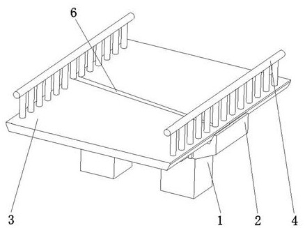
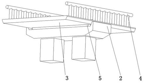
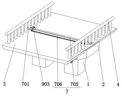
[0039] as attached image 3 to attach Figure 5 As shown, a damping deceleration mechanism for a bridge includes an adjusting device 7, and the adjusting device 7 includes a bottom plate 703 arranged along the width direction of the bridge plate 3 and used to be movably connected with the bridge plate 3. The side is also provided with a detachable assembly that can be connected with the fence 4 at the corresponding position. On the end surface of the bottom plate 703 away from its contact with the bridge plate 3, there are a plurality of vertically arranged first elastic springs that are distributed along the width direction of the bridge plate 3 and vertically arranged. member 704, in this embodiment, the first elastic member 704 is a first spring, and the adjustment device 7 also includes a deceleration plate 705 arranged along the width direction of...
PUM
 Abstract
Description
Claims
Application Information
PatSnap Eureka turns technology decisions into work you can execute. Powered by our Innovation Knowledge Graph, it runs expert workflows across engineering, life sciences, materials and intellectual property. Get your review-ready output in minutes.


