Municipal pipeline dredging device and use method thereof

A technology for dredging equipment and municipal pipelines, applied in water supply equipment, cleaning sewer pipes, waterway systems, etc., can solve problems such as unsatisfactory dredging effects, troublesome people's lives, excessive flow of sludge and sewage, etc., and achieve reasonable and ingenious structural design , Improve the scope of dredging and improve work efficiency

Pending Publication Date: 2021-06-15
陈丽阳
View PDF7 Cites 6 Cited by
  • Summary
  • Abstract
  • Description
  • Claims
  • Application Information

AI Technical Summary

Problems solved by technology

[0002] As an important project in urban construction, municipal pipelines involve a wide range of areas, mainly involving the laying of various urban pipelines. There are many types of these pipelines. After the laying is completed, regular maintenance and maintenance are required to ensure their normal production and operation. Among them, it is essential to clean these pipelines from sludge. Long-term use will cause a large amount of sludge to accumulate inside. come to trouble
[0003] Existing patent technology CN208604753U discloses a municipal pipeline dredging device. The device can adapt to pipelines of different diameters through the setting of rollers, slide bars and fixed columns, and the height and extension of the dredging plate can be adjusted by the cooperation of the motor and the hydraulic telescopic column. The discharge length is adjustable, but in the dredging process, the height and position of the dredging plate need to be adjusted continuously to complete the dredging of the pipeline at the same circumferential position, which makes the work efficiency low and the practicability is not high. In addition, the existing dredging device The nozzles are all fixedly installed on the device body, so that the position and range of the flowing water spraying are fixed, the dredging effect is not ideal, and the water consumption is relatively large, so we propose a municipal pipeline dredging device and its use method. to solve the above problems

Method used


Image

  • Municipal pipeline dredging device and use method thereof
  • Municipal pipeline dredging device and use method thereof
  • Municipal pipeline dredging device and use method thereof

Examples


Embodiment Construction

[0029] The following will clearly and completely describe the technical solutions in the embodiments of the present invention with reference to the accompanying drawings in the embodiments of the present invention. Obviously, the described embodiments are only some, not all, embodiments of the present invention.

[0030] In describing the present invention, it should be understood that the terms "upper", "lower", "front", "rear", "left", "right", "top", "bottom", "inner", " The orientation or positional relationship indicated by "outside", etc. is based on the orientation or positional relationship shown in the drawings, and is only for the convenience of describing the present invention and simplifying the description, rather than indicating or implying that the referred device or element must have a specific orientation, so as to Specific orientation configurations and operations, therefore, are not to be construed as limitations on the invention.

[0031] refer to Figure ...


PUM


Abstract

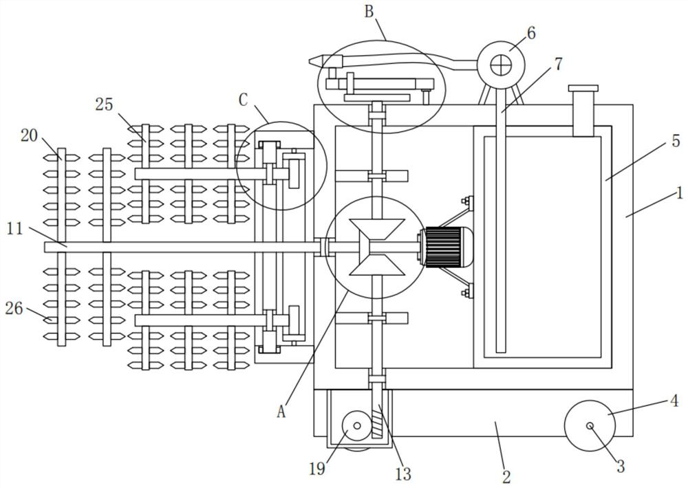
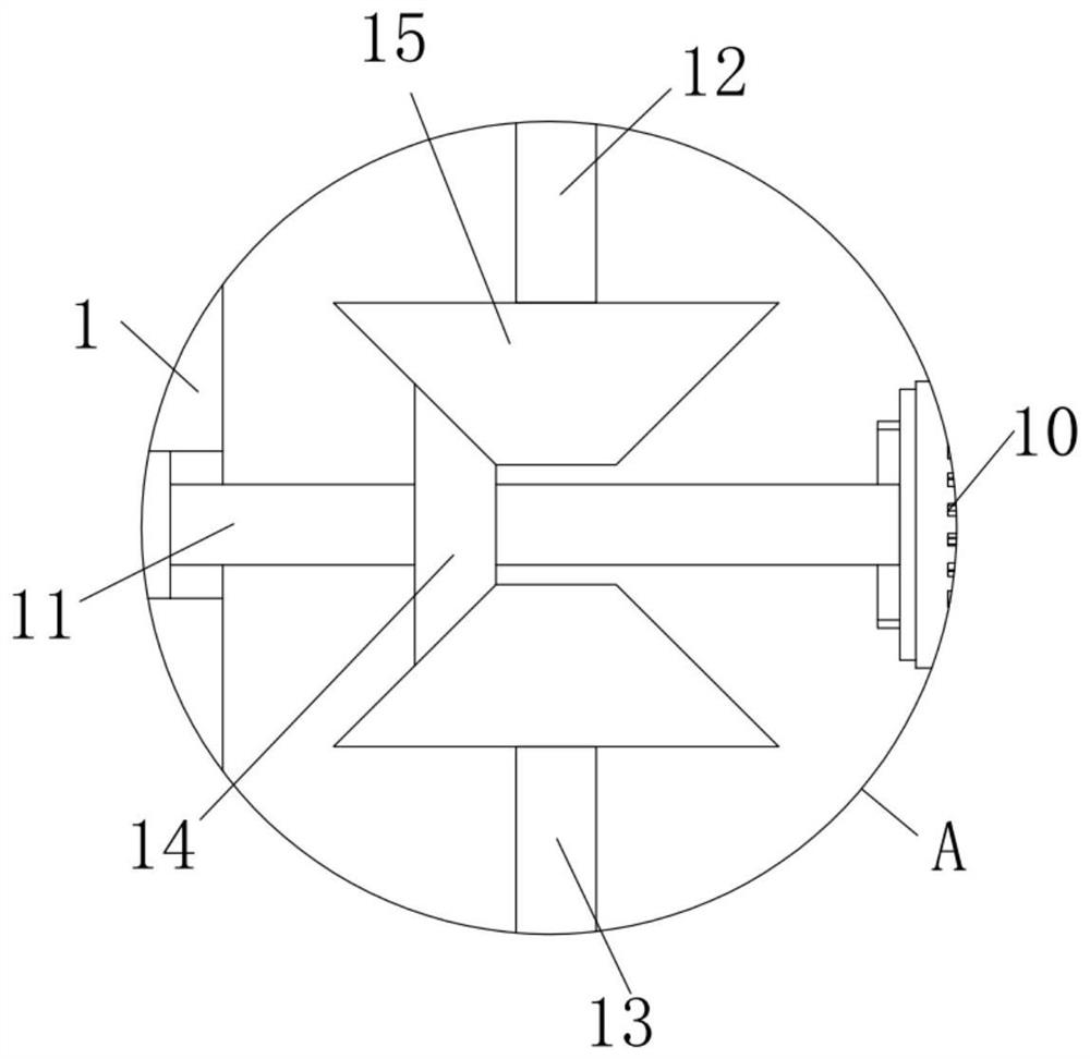
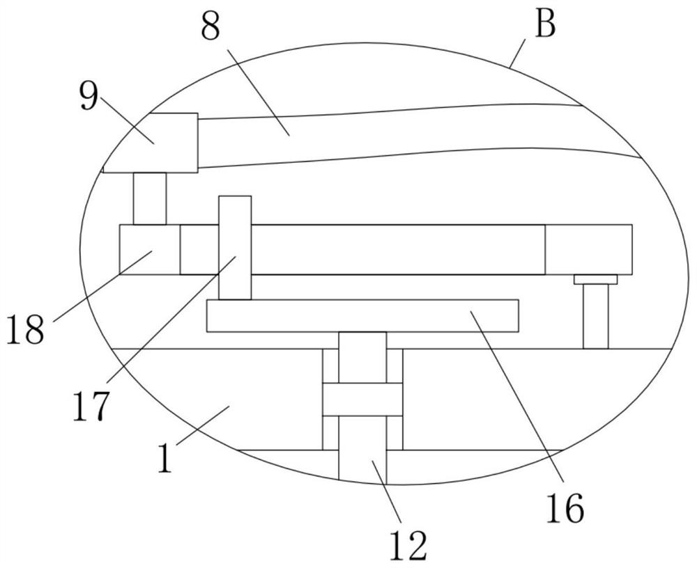
The invention relates to the technical field of pipeline dredging, and discloses a municipal pipeline dredging device and a use method thereof. The municipal pipeline dredging device comprises a box body, wherein two first rotating shafts are rotatably installed at the bottom of the box body, two rolling wheels are fixedly installed on the outer sides of the two first rotating shafts, a water tank is fixedly installed in the box body, a water pump is fixedly installed on the top of the box body, one end of a water pipe and one end of a hose are fixedly installed at the bottom and on one side of the water pump respectively, the other end of the water pipe extends into the water tank, the other end of the hose fixedly communicates with a spray head, a motor is fixedly installed on one side of the water tank, and one end of a second rotating shaft is fixedly connected to an output shaft of the motor. The municipal pipeline dredging device has the advantages of reasonable and clever structural design and convenience in use, and sludge in a municipal pipeline can be effectively diluted, so that the sludge can automatically circulate, and the dredging efficiency is improved.

Description

technical field [0001] The invention relates to the technical field of pipeline dredging, in particular to a municipal pipeline dredging device and a use method thereof. Background technique [0002] As an important project in urban construction, municipal pipelines involve a wide range of areas, mainly involving the laying of various urban pipelines. There are many types of these pipelines. After the laying is completed, regular maintenance and maintenance are required to ensure their normal production and operation. Among them, it is essential to clean these pipelines from sludge. Long-term use will cause a large amount of sludge to accumulate inside. come to trouble. [0003] Existing patent technology CN208604753U discloses a municipal pipeline dredging device. The device can adapt to pipelines of different diameters through the setting of rollers, slide bars and fixed columns, and the height and extension of the dredging plate can be adjusted by the cooperation of the ...

Claims


Application Information

Patent Timeline
Patent Type & Authority Applications(China)
IPC IPC(8): E03F9/00E03F7/10
CPCE03F9/00E03F7/10E03F9/002E03F7/106E03F7/103
Inventor 陈丽阳
Owner 陈丽阳
Why Eureka
Try Eureka