Small-diameter micro-resistivity scanning imager

A technology of micro-resistivity and scanning imaging, which is applied in the directions of measurement, borehole/well components, earthwork drilling and production, etc. It can solve the problems of poor heat dissipation performance of the acquisition module, short usable time, and low logging efficiency, so as to improve the logging efficiency. Well efficiency, low risk of fluid leakage and high reliability

Pending Publication Date: 2021-06-15
CHINA OILFIELD TECH SERVICES
View PDF1 Cites 1 Cited by
  • Summary
  • Abstract
  • Description
  • Claims
  • Application Information

AI Technical Summary

Problems solved by technology

However, since the electronic components also generate a certain amount of heat during the working process, the internal temperature of the acquisition module gradually rises, and the heat dissipation performance of the acquisition module is very poor, which leads to a single working time of the micro-resistivity scanning imager. time-limited
In the related art, when using the micro-resistivity

Method used


Image

  • Small-diameter micro-resistivity scanning imager
  • Small-diameter micro-resistivity scanning imager
  • Small-diameter micro-resistivity scanning imager

Examples


Example Embodiment

[0061] The following is attached Figure 1-10 The application is described in further detail.

[0062] The embodiment of the present application discloses a small-diameter micro-resistivity scanning imager.

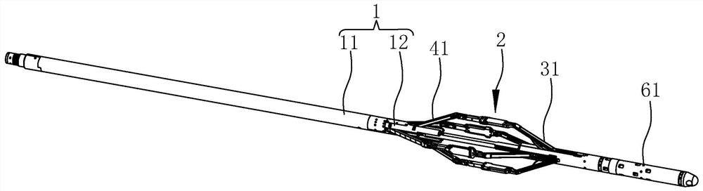
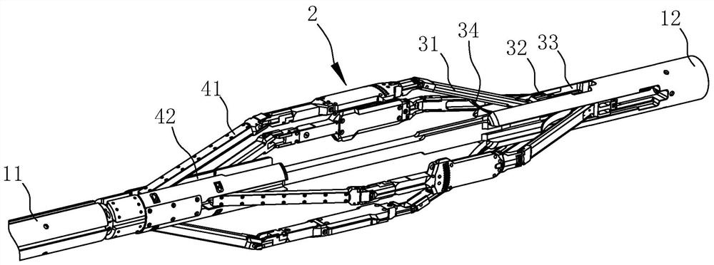
[0063] refer to figure 1 and figure 2 , the small-diameter micro-resistivity scanning imager includes a main rod 1 and several acquisition modules 2 . The main rod 1 includes a first rod 11 and a second rod 12 , the first rod 11 is a cylinder, and the second rod 12 extends into the first rod 11 and is fixedly connected with the first rod 11 . In this embodiment, four collection modules 2 are provided, and the four collection modules 2 are arranged circumferentially around the second rod 12, and the collection modules 2 are staggered in the axial direction of the second rod 12, and each collection module 2 Both are parallel to the main rod 1.

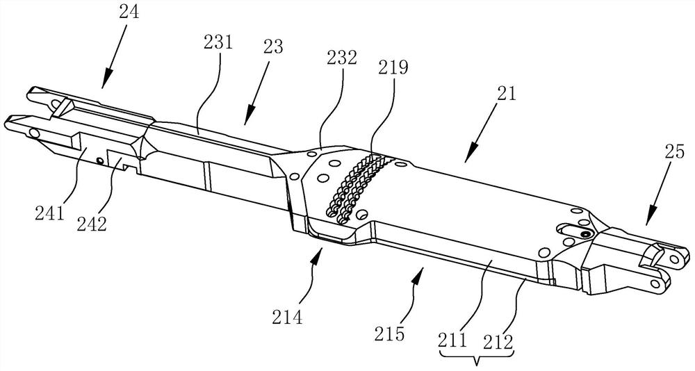
[0064] refer to image 3 and Figure 4 , the collection module 2 includes a collection plate 21 , a main arm connecting pi...


PUM


Abstract

The invention relates to a small-diameter micro-resistivity scanning imager. The small-diameter micro-resistivity scanning imager comprises a main rod piece and a plurality of acquisition modules arranged around the main rod piece in the circumferential direction, one ends of the acquisition modules are hinged to main arms, the other ends of the acquisition modules are hinged to auxiliary arms, the ends, away from the acquisition modules, of the main arms are hinged to the main rod piece, a mounting chamber is arranged in the main rod piece, a push-pull device is arranged in the mounting chamber, a part in the push-pull device extends out of the mounting chamber to be connected with the main arms so as to drive the main arms to rotate around the hinged positions between the main arms and the main rod piece, sliding pieces are hinged to the ends, away from the acquisition modules, of the auxiliary arms, the sliding pieces are slidably connected to the main rod piece in the length direction of the main rod piece, stability maintaining devices are connected to the sliding pieces, the stability maintaining devices apply force to the auxiliary arms to rotate around the hinged positions between the auxiliary arms and the sliding pieces in the direction away from the main rod piece, the acquisition modules are located between the push-pull device and the sliding pieces, and the main rod piece is provided with a hydraulic balancing device used for balancing the pressure intensity of liquid inside and outside the mounting chamber. The small-diameter micro-resistivity scanning imager has the advantages that well logging can be conducted in the descending process and the lifting process.

Description

technical field [0001] The present application relates to the field of logging equipment, in particular to a small-diameter micro-resistivity scanning imager. Background technique [0002] With the steady increase in the demand for oil in various countries in the world, in order to enhance the exploration ability and improve the development efficiency under complex conditions, it is urgent to understand the characteristics of various aspects of oil and gas reservoirs more accurately. [0003] The main advantage of the micro-resistivity scanning imager is that it can provide images of the resistivity of the formation near the borehole wall as a function of depth, and it has unique advantages in detecting complex lithology and fractured oil and gas reservoirs. When using the micro-resistivity scanning imager for well logging, it is necessary to place the micro-resistivity scanning imager in the well, then control the pusher to push the acquisition module against the well wall,...

Claims


Application Information

Patent Timeline
IPC IPC(8): E21B49/00E21B47/00
CPCE21B47/00E21B49/00
Inventor 张宝辉李东生颜肖平张学林
Owner CHINA OILFIELD TECH SERVICES
Why Eureka
Try Eureka