Device for detecting sewage permeation condition of refuse landfill

A technology for landfills and sewage, applied in measuring devices, permeability/surface area analysis, suspension and porous material analysis, etc., can solve problems such as inaccurate detection results, increase practicability, ease of use, and ease of use The effect of promotion and use

Pending Publication Date: 2021-06-15
重庆三鑫环保标志有限公司
View PDF1 Cites 0 Cited by
  • Summary
  • Abstract
  • Description
  • Claims
  • Application Information

AI Technical Summary

Problems solved by technology

[0002] After the garbage is landfilled, chemical reactions will occur to produce chemical sewage, and the rainwater will seep into the landfill after it rains, thus forming sewage. In order to prevent the sewage from penetrating into the soil below, it is necessary to carry out anti-seepage treatment on the landfill. For example, in the patent with the publication number CN208860711U, the moto

Method used


Image

  • Device for detecting sewage permeation condition of refuse landfill
  • Device for detecting sewage permeation condition of refuse landfill
  • Device for detecting sewage permeation condition of refuse landfill

Examples


Embodiment 1

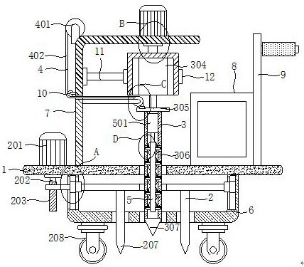
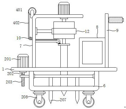
[0027] see Figure 1-7 , the present invention provides a technical solution: a device for detecting sewage infiltration in landfills, including a working board 1, a fixing mechanism 2 is arranged below the working board 1, and a rotating mechanism 3 is arranged above the working board 1 , the transmission mechanism 4 and the detection mechanism 5, the bottom of the working board 1 is fixedly equipped with a fixed frame 6, the top of the working board 1 is fixedly installed with a right-angle plate 7, and the top of the working board 1 is fixedly installed with a detection display 8.

[0028] Further, the top of the working board 1 is fixedly installed with a vertical rod 9, and a handle is fixedly installed on one side of the outer wall of the vertical rod 9, and the outer wall of the handle is provided with a non-slip sleeve to facilitate the movement of the device.

Embodiment 2

[0030] see Figure 1-7, on the basis of Embodiment 1, the fixing mechanism 2 includes a first motor 201, a rotating shaft 202, a threaded rod 203, a chute 204, a slider 205, a lifting plate 206, a fixed long needle 207 and a walking wheel 208, and the working plate 1 The top of the working plate 1 is fixedly installed with a first motor 201, and the bottom of the working plate 1 is rotatably equipped with a rotating shaft 202. The output shaft of the first motor 201 extends to the bottom of the working plate 1 through a coupling and is fixedly connected with the rotating shaft 202. The rotating shaft One end of 202 is fixedly installed with threaded rod 203, and the inner wall of both sides of fixed mount 6 is all provided with chute 204, and the inside of two groups of chute 204 is slidingly installed with slide block 205, and one side outer wall of fixed mount 6 is provided with opening, wherein One side outer wall of one group of slide block 205 is fixedly installed with mo...


PUM


Abstract

The invention discloses a device for detecting the sewage permeation condition of a refuse landfill, which relates to the technical field of refuse landfill. The device for detecting the sewage permeation condition of the refuse landfill comprises a working plate, a fixing mechanism is arranged below the working plate, and a rotating mechanism, a transmission mechanism and a detection mechanism are arranged above the working plate. According to the device for detecting the sewage permeation condition of the refuse landfill, through cooperative use of an electric push rod, a convex long plate, a mounting rod, a mounting block, a probe and a detection display, the permeation conditions of different heights at the same position can be detected, a detection result can be conveniently observed, starting of a motor does not need to be controlled for multiple times, and the permeation conditions of different heights at the same position are detected, so that the detection efficiency is improved, meanwhile, the permeation conditions of different heights at the same position are conveniently compared, the practicability is high, and the detection result is more accurate.

Description

technical field [0001] The invention relates to the technical field of garbage landfill, in particular to a device for detecting the seepage of sewage in a garbage landfill. Background technique [0002] After the garbage is landfilled, chemical reactions will occur to produce chemical sewage, and the rainwater will seep into the landfill after it rains, thus forming sewage. In order to prevent the sewage from penetrating into the soil below, it is necessary to carry out anti-seepage treatment on the landfill. For example, in the patent with the publication number CN208860711U, the motor drives the screw to rotate, thereby driving the probe into the bottom, and then detecting the sewage infiltration of the landfill site. However, this method cannot detect the infiltration at different heights at the same position, and requires The starting of the motor is controlled, and the soil is dropped together with the rotating probe during the rotation process, thus making the detecti...

Claims


Application Information

Patent Timeline
IPC IPC(8): G01N15/08
CPCG01N15/0806
Inventor 张姝王闯李茵茹何松洋
Owner 重庆三鑫环保标志有限公司
Why Eureka
Try Eureka