Vacuum cleaner

A technology for vacuum cleaners and vacuum motors, which is applied to the installation of vacuum cleaners, instruments, and electrical equipment, and can solve problems such as failure to provide optimal performance and damage to machines

Pending Publication Date: 2021-06-15
DYSON TECH LTD
View PDF6 Cites 4 Cited by
  • Summary
  • Abstract
  • Description
  • Claims
  • Application Information

AI Technical Summary

Problems solved by technology

In the former case, users may be frustrated by the time it takes to read, while in the latter case, users may damage their machines or unknowingly use them in a way that does not provide optimal performance

Method used


Image

  • Vacuum cleaner
  • Vacuum cleaner
  • Vacuum cleaner

Examples


Embodiment Construction

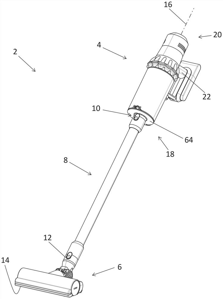
[0062] figure 1 A stick vacuum cleaner 2 according to an embodiment of the invention is shown. The stick vacuum cleaner 2 comprises a hand-held vacuum cleaner 4 connected by an elongate rigid stick 8 to a floor tool 6 in the form of a cleaning head. In this case, the wand can be attached to the air inlet 10 of the hand-held vacuum cleaner and the rear duct 12 of the cleaning head. The wand 8 is generally tubular, the space inside forming a suction path extending from the cleaning head 6 to the air inlet 10 of the hand-held vacuum cleaner 4 .

[0063] The cleaning head 6 has a base plate 14 which is configured to engage the floor surface and which has a suction opening (not visible) through which dirty air (i.e. air entrained with dirt) from the floor surface can be drawn into the cleaning head 6 in. In use, a vacuum motor (not shown) housed in the hand-held vacuum cleaner 4 generates suction at the air inlet 10 . Dirty air from the floor surface is sucked into the cleaning...


PUM


Abstract

A vacuum cleaner comprises a vacuum motor configured to draw an air flow through an air flow path of the vacuum cleaner; a dirt separator having dirt receptacle; a display screen; and a controller configured to control images displayed on the screen. The dirt receptacle has a closed configuration in which it can receive dirt separated from the air flow, and an open configuration in which dirt contained in the dirt receptacle can be emptied therefrom. The controller is configured to display video instructions on the screen.

Description

technical field [0001] The present invention relates to vacuum cleaners. Background technique [0002] Modern vacuum cleaners are often relatively complex, as manufacturers are always looking to offer additional or improved features. As a result, many vacuum cleaners now require the user to perform a relatively complex procedure in order to use them properly. As a result, the operation of many vacuum cleaners is no longer a matter of simple intuition. As a result, users are forced to read instruction manuals, or use trial and error to figure out how to operate their vacuum cleaners. In the former case, users may be frustrated by the time it takes to read, while in the latter case, users may damage their machines or unknowingly use them in a way that does not provide optimal performance . Contents of the invention [0003] It is an object of the present invention to alleviate or eliminate at least one of the above disadvantages and / or to provide an improved or alternati...

Claims


Application Information

Patent Timeline
Patent Type & Authority Applications(China)
IPC IPC(8): A47L5/22A47L5/24A47L9/28
CPCA47L5/24A47L5/225A47L9/2857A47L9/2836A47L5/28A47L9/1683A47L9/248G06F3/14G09B5/065G09B19/003
Inventor K.金N.劳森麦克利恩A.霍尔登E.巴尔德里
Owner DYSON TECH LTD
Why Eureka
Try Eureka