Braking control device

A braking control and braking force technology, applied in the direction of brakes, ESP control systems, etc., can solve problems such as changes in comfort

Pending Publication Date: 2021-06-15
ADVICS CO LTD
View PDF6 Cites 2 Cited by
  • Summary
  • Abstract
  • Description
  • Claims
  • Application Information

AI Technical Summary

Problems solved by technology

In this case, although the stability of the vehicle can be ensured, the comfort inside the vehicle may change rapidly.

Method used


Image

  • Braking control device
  • Braking control device
  • Braking control device

Examples


Embodiment Construction

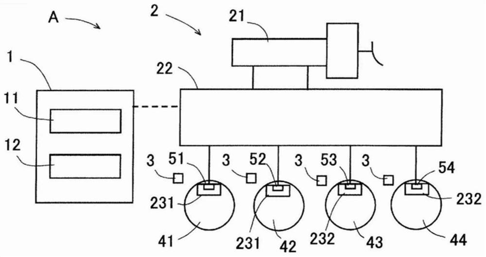
[0012] Hereinafter, embodiments of the present invention will be described based on the drawings. Each drawing used in the explanation is a schematic diagram. Such as figure 1 As shown, the vehicle brake device A according to this embodiment includes a brake control device 1 , a braking force generator 2 , a wheel speed sensor 3 , and wheels 41 , 42 , 43 , and 44 . For example, the wheel 41 is a right front wheel, the wheel 42 is a left front wheel, the wheel 43 is a right rear wheel, and the wheel 44 is a left rear wheel. The wheel speed sensor 3 is a sensor for detecting wheel speed, and is provided for each of the wheels 41 to 44 . The wheel speed sensor 3 transmits wheel speed information, which is a detection result, to the brake control device 1 . The braking force generator 2 is a well-known device, and an example will be briefly described below.

[0013] The braking force generating device 2 is a device that generates frictional braking force (hydraulic braking for...


PUM


Abstract

A brake control device of the present invention is provided with a first control unit (11) that, when the deceleration of a vehicle is increased, increases a target braking force, which is either a front wheel braking force applied to front wheels (41, 42) of the vehicle or a rear wheel braking force applied to rear wheels (43, 44) of the vehicle, and executes a first control for reducing the object braking force; and a second control unit (12) that, prior to execution of the first control, executes second control that decreases the increase gradient of the target braking force and increases the increase gradient of the front wheel braking force or the rear wheel braking force that is not the target braking force.

Description

technical field [0001] The invention relates to a brake control device. Background technique [0002] Among the brake control devices, there is a device that executes pitch suppression control that suppresses pitch during braking so that passengers can spend comfortably in the vehicle. For example, the braking force control device described in Japanese Patent Laid-Open No. 2017-109664 executes pitching suppression control in which the braking force applied to the rear wheels is larger than the braking force based on the braking force distribution in a dive state. Thereby, it is possible to suppress the tendency of diving during braking, and to improve ride comfort during braking. [0003] Patent Document 1: Japanese Patent Laid-Open No. 2017-109664 [0004] However, in the conventional device, in a vehicle state where anti-skid control (ABS control) should be executed, the execution of anti-skid control is prioritized, and the execution of specific control such as pitching...

Claims


Application Information

Patent Timeline
Patent Type & Authority Applications(China)
IPC IPC(8): B60T8/1755B60T8/26B60T8/28
CPCB60T8/1755B60T8/26B60T8/28B60T8/329B60T8/1766B60T8/245B60T8/58B60T2240/00B60T2250/04B60T2270/30
Inventor 山本勇作
Owner ADVICS CO LTD
Why Eureka
Try Eureka