Outdoor power equipment unit with condition responsive electronic control of traction drive system

a technology of electronic control and traction drive system, which is applied in the direction of fluid couplings, instruments, couplings, etc., can solve the problems of reducing the quality of cut being provided by the mower, the insufficient horsepower of the available engine, and the rise or fall of the load demands on the engine, so as to reduce enhance the continued ability of the work implement. , the effect of reducing the load of the prime mover

Active Publication Date: 2014-11-04
TORO CO THE
View PDF10 Cites 19 Cited by
  • Summary
  • Abstract
  • Description
  • Claims
  • Application Information

AI Technical Summary

Benefits of technology

[0011]One aspect of this invention relates to an outdoor power equipment unit which comprises a frame carrying a work implement for performing a ground or turf grooming or working operation. The frame also carries a prime mover whose speed is set by an operator using an adjustable throttle. A traction drive system driven by the prime mover is provided for moving the frame over the ground at an adjustable ground speed that is established by a setting provided by an operator using an adjustable speed control. An implement drive system is driven by the prime mover for moving the work implement in a grooming or working operation. A fan drive system is driven by the prime mover for powering a cooling fan that cools one fluid in at least one cooling system carried on the frame. A sensor provides an indicator of prime mover load during the working operation being performed by the work implement. A sensor provides a temperature reading of the fluid during the working operation being performed by the work implement. An electronic controller is also provided for receiving the prime mover load indicator and temperature inputs from the sensors and for regulating the ground speed of the frame when the prime mover load indicator input is greater than a predetermined percentage of prime mover full load. The electronic controller regulates the speed of the frame by automatically reducing an output speed of at least one variable speed member contained in the traction drive system to reduce the ground speed of the frame without requiring that the speed control setting established by the user through the position of the speed control be manually changed by the user, by automatically shutting off the cooling fan for periods of time that the temperature input is below a predetermined first limit thereof but resuming operation of the cooling fan when the temperature input reaches or exceeds the first limit thereof, and by maintaining the automatically reducing and automatically shutting off actions until the prime mover load indicator input drops back below the predetermined percentage of prime mover full load.
[0012]Another aspect of this invention relates to an outdoor power equipment unit that comprises a frame carrying a work implement for performing a ground or turf grooming or working operation. The frame also carries a prime mover whose speed is set by an operator using an adjustable throttle. A traction drive system is driven by the prime mover for moving the frame over the ground at an adjustable ground speed that is established by an operator using an adjustable speed control. An implement drive system driven by the prime mover is provided for moving the work implement in a grooming or working operation. A fan drive system driven by the prime mover is provided for powering a cooling fan that cools one fluid in at least one cooling system carried on the frame. A first sensor provides an indicator of prime mover load during the working operation being performed by the work implement. A second 1 sensor provides an indicator of work implement load during the working operation being performed by the work implement. A temperature sensor provides a temperature reading of the fluid during the working operation being performed by the work implement. An electronic controller receives the prime mover load indicator, the work implement load indicator, and temperature inputs from the sensors and automatically reduces an output speed of at least one variable speed member contained in the traction drive system to reduce the ground speed of the frame without requiring that the speed control setting established by the operator through the position of the speed control be manually changed by the operator. The controller does this whenever the following conditions are present: 1.) when the prime mover load indicator input is greater than a predetermined percentage of prime mover full load to thereby reduce prime mover load to enhance the continued ability of the work implement to conduct the grooming or working operator; and 2.) additionally either when the work implement load indicator input reaches or exceeds a limit to thereby reduce prime mover load to prevent damage to the work implement or when the temperature input reaches or exceeds a limit to reduce prime mover load to prevent damage to the cooling system or any components cooled thereby.

Problems solved by technology

One difficulty experienced in the operation of outdoor power equipment units of this type is that the load experienced by the work implements can vary widely over a short period of time, thus causing the load demands on the engine to rise or fall quickly as well.
When this happens, the available engine horsepower may be insufficient to both maintain the vehicle speed and to cut the longer and thicker grass properly.
If the operator tries to maintain the mower ground speed at the same speed when cutting longer and thicker grass as when cutting shorter and sparser grass, then the quality of cut being provided by the mower will decline.
In other words, the grass will not be cut as evenly and uniformly as before at and after the point at which the available engine horsepower is fully utilized.
However, this latter approach requires a very skilled operator who is constantly attentive to engine lug to be even somewhat successful.
Even with a skilled and attentive operator, the inevitable slow response time of a human being means that the available engine horsepower is still often exceeded when the instantaneous traction drive and work implement loads are greater than that horsepower—the operator tends to react too slowly.
The situation is even worse when a less experienced or skilled operator is operating the mower.
However, in an outdoor power equipment unit, this only exacerbates the situation by increasing the load imposed by the traction drive system.
The result is an engine stall and a complete stoppage of the mower.
However, a system as disclosed in Evans is incapable of addressing every load situation experienced during the operation of the outdoor power equipment unit.
There will be times when the load imposed by the work implements may be so extreme that it would require slowing the ground speed too much, thereby creating an unsafe operational condition.

Method used


Image

  • Outdoor power equipment unit with condition responsive electronic control of traction drive system
  • Outdoor power equipment unit with condition responsive electronic control of traction drive system
  • Outdoor power equipment unit with condition responsive electronic control of traction drive system

Examples


Embodiment Construction

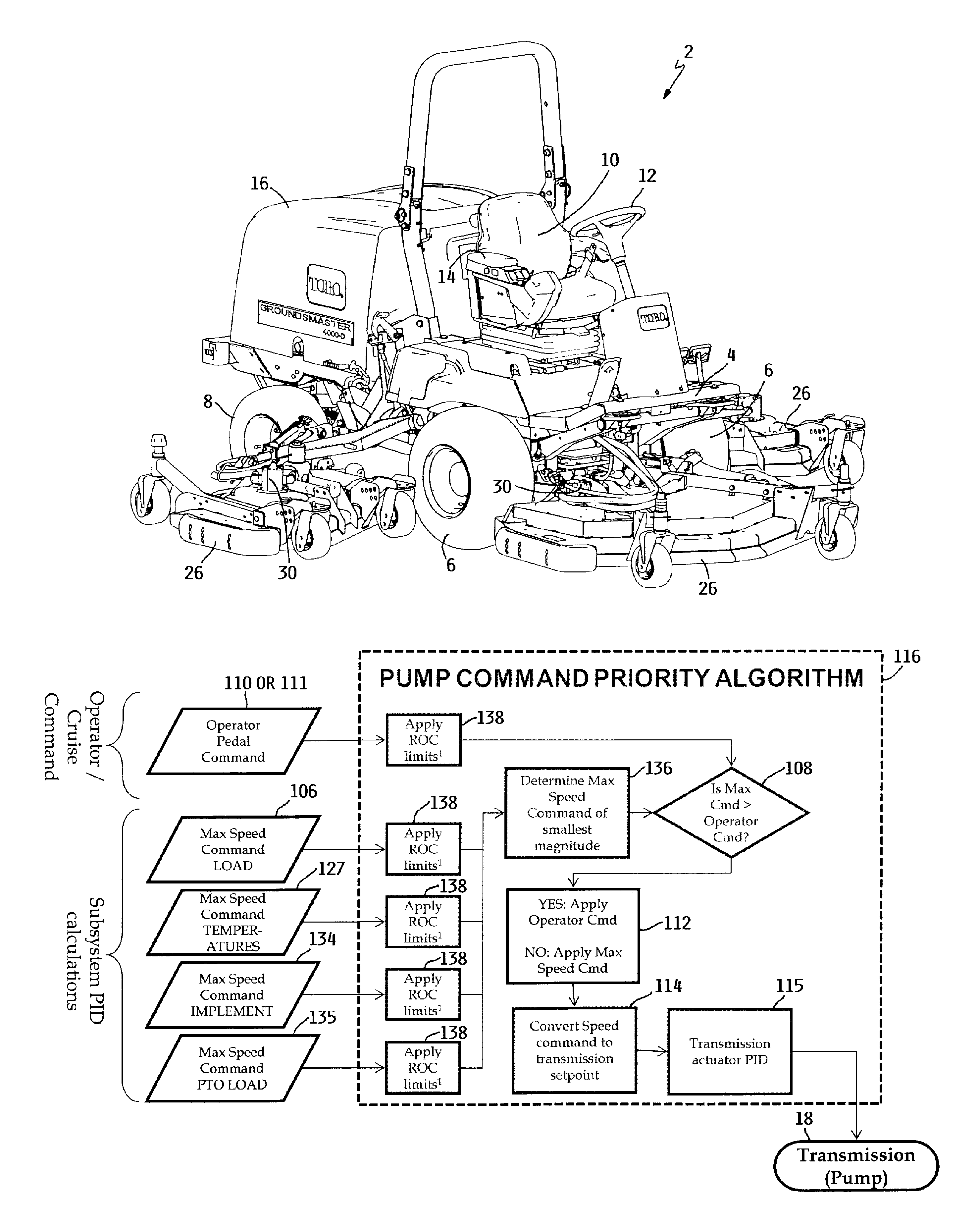
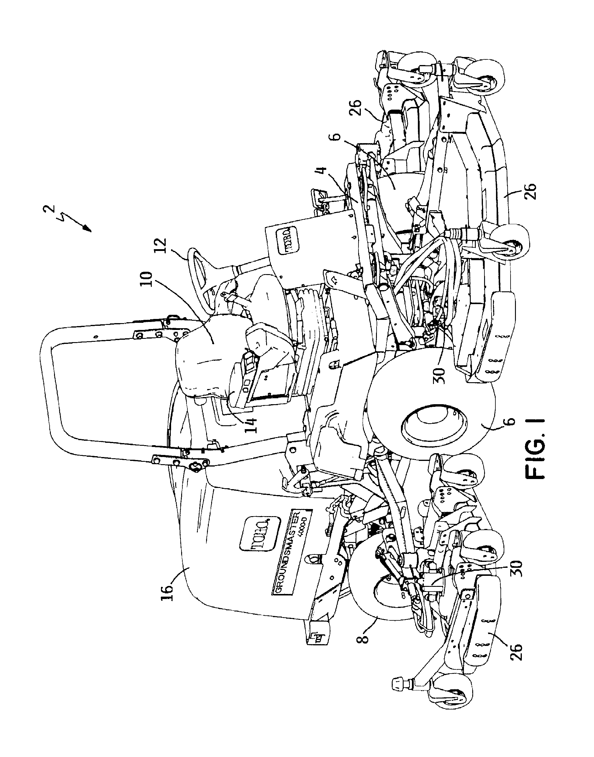
[0018]FIG. 1 is a perspective view of one type of outdoor power equipment unit that may effectively utilize the control system and method of this invention. The specific outdoor power equipment unit shown in FIG. 1 comprises a mower 2. Mower 2 includes a frame 4 that is supported for movement over the ground by a pair of front wheels 6 and a pair of rear wheels 8. Frame 4 includes an operator's station having a seat 10 for supporting a seated operator, a steering wheel 12 that the operator uses to steer and guide mower 2, and a control console 14 having various controls for controlling the operation of various components of mower 2. Frame 4 also carries a prime mover thereon, such as an internal combustion engine 15 (FIG. 2), that is positioned behind the operator's station and that is enclosed within an engine cowl or hood 16. The prime mover could alternatively comprise an electric motor that is powered by a battery pack, or by an engine generator / battery pack hybrid system, or by...


PUM


Abstract

An outdoor power equipment unit comprises a self-propelled mower having a hydraulic traction drive system. When engine load exceeds a predetermined percentage of full load, a controller automatically reduces the stroke of a variable displacement pump in the traction drive system to reduce the ground speed of the mower without the operator having to change the position of the traction pedal. This reduces engine load to enhance continued good cutting performance. At any time, the controller can take the same actions to reduce ground speed if an excessively high temperature in a fluid used in a cooling system on the mower is detected, or if excessive loads on the mower decks of the mower are detected, or both.

Description

TECHNICAL FIELD[0001]This invention relates to outdoor power equipment units which are self-propelled by a hydraulic traction drive system operated by a prime mover such as an internal combustion engine. More particularly, this invention relates to a control system for maximizing the efficient use of engine horsepower over widely varying load conditions imposed on the engine by a work implement carried by such an outdoor power equipment unit.BACKGROUND OF THE INVENTION[0002]The field of outdoor power equipment comprises a wide variety of units that perform various types of work operations in an outdoor environment. A common characteristic of such units is that they carry a prime mover of some type thereon that powers a traction drive system. In turn, the traction drive system powers one or more ground engaging traction drive members, such as wheels or endless tracks, which cause the unit to be self-propelled over the ground.[0003]The traction drive systems of outdoor power equipment...

Claims


Application Information

Patent Timeline
Patent Type & Authority Patents(United States)
IPC IPC(8): A01D34/66E02F3/04G06F7/70A01D34/00
CPCA01D34/66A01D34/006A01D34/80F16H61/468A01D69/005F16H61/431F16H61/475F16H2059/6838
Inventor GAMBLE, JESSE R.BJORKMAN, KYLE C.FRICK, ALEXANDER S.
Owner TORO CO THE
Why Eureka
Try Eureka