Overhead door mechanism of wall cupboard and wall cupboard

A hanging cabinet and flip door technology, applied in the field of hanging cabinets, can solve the problems that the open area cannot meet the needs of users, the maximum height of the flip door cannot meet the needs of users, etc., to improve the user experience, simple structure, and increase the height of the flip Effect

Pending Publication Date: 2021-06-18
ZHEJIANG JIECHANG LINEAR MOTION TECH
View PDF1 Cites 1 Cited by
  • Summary
  • Abstract
  • Description
  • Claims
  • Application Information

AI Technical Summary

Problems solved by technology

The upturn height of the existing flap is limited by the length of the first connecting rod. When it is necessary to increase the upturn height of the flap, the length of the first connecting rod needs to be increased. Due to the limited depth of the outer cabinet, the first connecting rod cannot be unlimited Therefore, the use of the existing door flap mechanism will cause the maximum height of the flap door to be turned up and cannot meet the user's needs, which will lead to the area where the opening is opened cannot meet the user's needs

Method used


Image

  • Overhead door mechanism of wall cupboard and wall cupboard
  • Overhead door mechanism of wall cupboard and wall cupboard
  • Overhead door mechanism of wall cupboard and wall cupboard

Examples


Embodiment 1

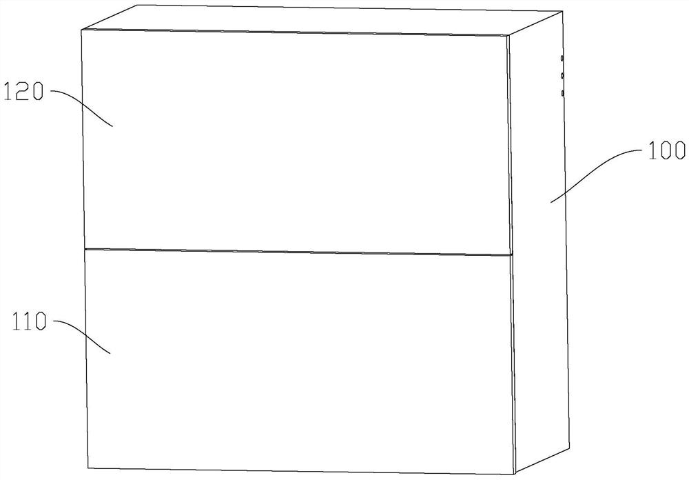
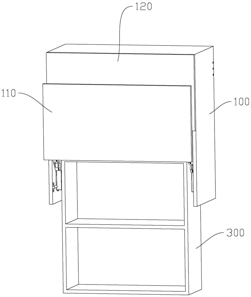
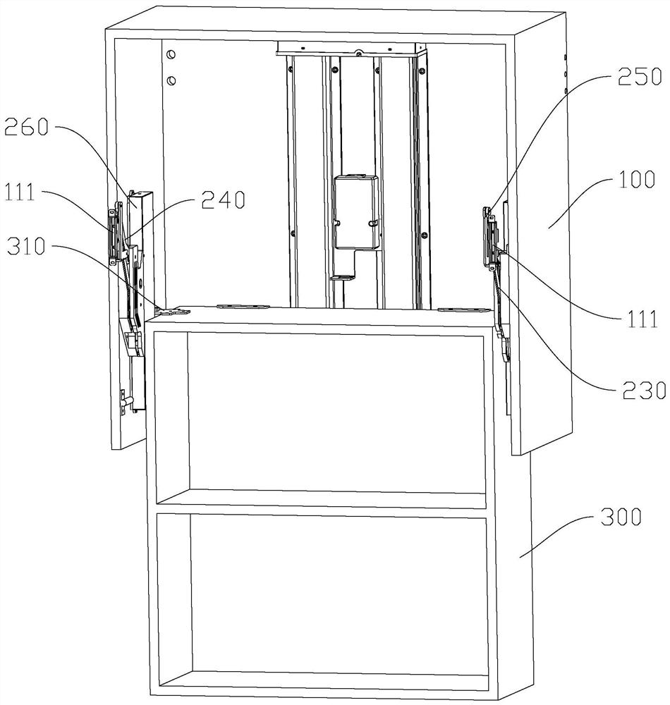
[0041] refer to Figure 1 to Figure 7 As shown, the hanging cabinet in this embodiment includes an outer cabinet 100, the front side of the outer cabinet 100 is provided with an opening and a flip door 110 corresponding to the opening, and a flip door is respectively provided on the inner walls of the two side walls of the outer cabinet Mechanism 200, two flap mechanisms 200 are symmetrically arranged, the flap mechanism can drive the flap 110 to open and close the opening, and the flap mechanism 200 includes a rack 210, a gear 220 meshing with the rack 210, and an active mechanism that rotates synchronously with the gear 220. The rod 230, the driven rod 240 hinged on the inner wall of the side wall of the outer cabinet, and the connecting rod 250 connecting the driving rod 230 and the driven rod 240, the driving rod 230, the driven rod 240 and the connecting rod 250 constitute a parallelogram mechanism, and the connecting rod 250 It is fixedly connected with the flip door 110...

Embodiment 2

[0054] Compared with the first embodiment, the difference of this embodiment is that the hanging cabinet also includes an electric lifting mechanism for driving the inner cabinet 300 to rise and fall. The electric lifting mechanism includes a motor and a screw drive assembly, and the motor is fixed on the outer cabinet. On the inner wall of the back plate, the screw drive assembly includes a vertically arranged drive screw and a drive nut threaded with the drive screw. The drive nut is fixedly connected to the inner cabinet, and the motor drives the drive screw to rotate to make the drive nut move up and down. The drive nut moves up and down to drive the inner cabinet to rise and fall, thereby realizing automatic control of the lifting and lowering of the inner cabinet 300 and improving the user experience.

[0055] It can be understood that, in other embodiments of the present invention, the electric lifting mechanism can also use the lifting adjustment assembly in CN202011197...

Embodiment 3

[0058] Compared with Embodiments 1 and 2, the difference of this embodiment is that the hanging cabinet in this embodiment only includes an outer cabinet, the bottom of the outer cabinet is closed and used for storing articles, and the front side of the outer cabinet is provided with an opening and an outer cabinet. For the flip door corresponding to the opening, an electric push rod for driving the rack 210 to slide up and down is fixed on the inner wall of the side wall of the outer cabinet. This design can save the lifting of the inner cabinet and the lifting mechanism that drives the lifting of the inner cabinet, and can directly realize the opening and closing action of the parallel flip door on the outer cabinet.


PUM


Abstract

The invention discloses an overhead door mechanism of a wall cupboard and the wall cupboard, and solves the technical problem that the maximum upturning height of an overhead door in the prior art cannot meet the requirements of a user. The overhead door mechanism of the wall cupboard comprises an outer cupboard, and the front side of the outer cupboard is provided with an opening and the overhead door corresponding to the opening, the overhead door mechanism comprises a rack, a gear meshed with the rack, a driving rod synchronously rotating with the gear, a driven rod hinged to the inner wall of the side wall of the outer cabinet and a connecting rod connecting the driving rod and the driven rod, the driving rod, the driven rod and the connecting rod form a parallelogram mechanism, and the connecting rod is fixedly connected with the overhead door, the rack is vertically and slidably installed on the inner wall of the outer cabinet side wall, the rack is driven to slide up and down so that the gear can rotate, and the gear rotates and drives the parallelogram mechanism to swing so that the overhead door can open and close the opening. In addition, the invention further discloses a wall cupboard adopting the overhead door mechanism.

Description

【Technical field】 [0001] The invention relates to the technical field of hanging cabinets, in particular to a door-turning mechanism of the hanging cabinet and the hanging cabinet. 【Background technique】 [0002] The door flap mechanism in the prior art includes a first connecting rod and a second connecting rod, one end of the second connecting rod is fixed on the inner wall of the side wall of the outer cabinet, the middle part of the first connecting rod is hinged on the other end of the second connecting rod, and the first connecting rod is hinged on the other end of the second connecting rod. One end of a connecting rod is hinged on the flip door, and the other end of the first connecting rod is a free end that cooperates with the wing plate. When the wing plate drives the free end of the first connecting rod to move downward, the first connecting rod is hinged with the flip door. The end drives the flap to move upward and outward. The flip-up height of the existing fl...

Claims


Application Information

Patent Timeline
Patent Type & Authority Applications(China)
IPC IPC(8): A47B51/00A47B97/00E06B5/00E06B3/40E05F11/54
CPCA47B51/00A47B97/00E06B5/006E06B3/40E05F11/54A47B2051/005E06B2003/403
Inventor 何立东
Owner ZHEJIANG JIECHANG LINEAR MOTION TECH
Why Eureka
Try Eureka