An electric lifting cabinet

A lifting and hanging cabinet technology, applied in the field of hanging cabinets, can solve the problems such as the inability to further reduce the descending stroke of the inner cabinet and the inability to meet the needs of users with the maximum height, and achieve the effects of improving stability, compact lifting mechanism, and improving bearing capacity.

Active Publication Date: 2022-04-19
ZHEJIANG JIECHANG LINEAR MOTION TECH
View PDF0 Cites 0 Cited by
  • Summary
  • Abstract
  • Description
  • Claims
  • Application Information

AI Technical Summary

Problems solved by technology

It can be seen that the turning-up height of the existing flap is limited by the length of the first connecting rod. When the turning-up height of the flap needs to be increased, the length of the first connecting rod needs to be increased. Because the depth of the outer cabinet is limited, the first The connecting rod cannot be extended infinitely, so the use of the existing door flap mechanism will cause the maximum height of the flap door to be turned up and cannot meet the user's needs, and then the top of the opening cannot be set too high, that is, the descending stroke of the inner cabinet cannot be further reduced

Method used


Image

  • An electric lifting cabinet
  • An electric lifting cabinet
  • An electric lifting cabinet

Examples


Embodiment 1

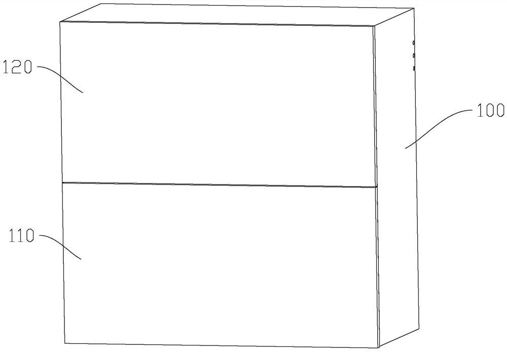
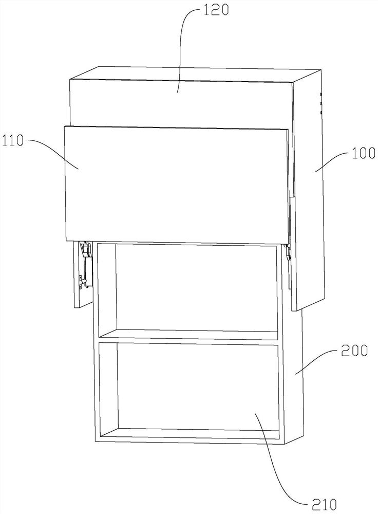
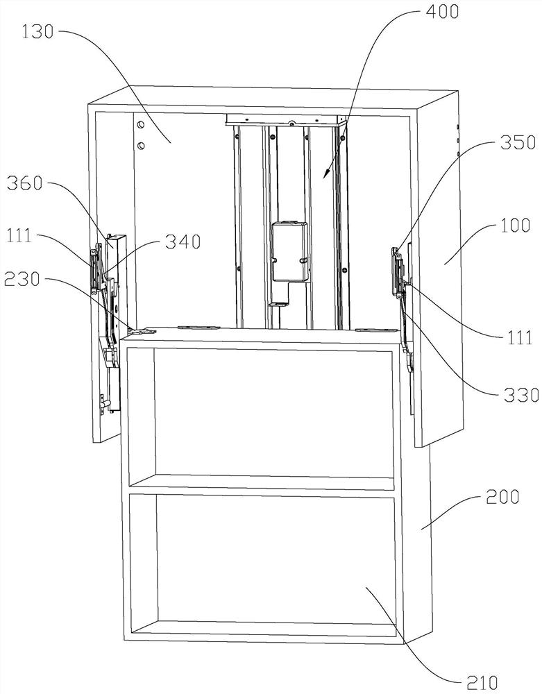
[0051] refer to Figure 1 to Figure 11 As shown, the electric liftable wall cabinet in this embodiment includes an outer cabinet 100 and an inner cabinet 200. The bottom of the outer cabinet 100 is opened to form an entrance and exit for the inner cabinet 200 to enter and exit. In the lifting mechanism 400 that drives the inner cabinet 200 to rise and fall, the lifting mechanism 400 drives the inner cabinet 200 to descend and expose downward through the entrance and exit, so as to be exposed to the outside of the outer cabinet 100; or the lifting mechanism 400 drives the inner cabinet 200 to rise and enter the outer cabinet through the entrance and exit. Inside the cabinet 100 to be stored inside the outer cabinet 100, the lifting mechanism 400 includes a motor 410, two gear boxes 420, and two lifting columns 430 arranged in parallel. The motor 410 includes an output shaft, and the two ends of the output shaft pass through the two gear boxes respectively. 420 is connected with...

Embodiment 2

[0078] Compared with Embodiment 1, the lifting column in this embodiment is a three-section lifting column, including a screw drive assembly and a three-section telescopic sleeve, wherein the screw drive assembly includes an inner screw rod, and a hollow socket outside the inner screw rod. Screw, inner drive nut and outer drive nut, the inner screw rod and the hollow screw rod rotate synchronously and cooperate with the hollow screw rod in axial expansion and contraction, the inner screw rod and the inner drive nut are screwed together, and the hollow screw rod is rotatable with the inner drive nut in the axial direction Upper positioning, the outer wall of the hollow screw is provided with an external thread that matches the outer drive nut, and the three-section telescopic sleeve includes an inner tube, an outer tube, and a middle tube that are sequentially set, the inner tube is set on the outer side of the hollow screw, the inner tube and the outer cabinet The top wall of t...


PUM


Abstract

The invention discloses an electric lifting hanging cabinet, which comprises an outer cabinet and an inner cabinet, a lifting mechanism is arranged between the outer cabinet and the inner cabinet, an opening is arranged on the front side of the outer cabinet, a fixed door is fixed above the opening, Corresponding to the flap door that is open and spliced ​​with the fixed door, the flap mechanism is fixed on the outer cabinet. The lifting mechanism includes a motor, two gearboxes, and two lifting columns. The motor is connected to the two lifting columns through the two gearboxes. A lifting column stretches to drive the inner cabinet up and down; the door flap mechanism includes a rack, a gear meshing with the rack, a driving rod that rotates synchronously with the gear, a driven rod hinged on the inner wall of the outer cabinet side wall, and connecting the driving rod and the driven rod. The connecting rod, the active rod, the driven rod and the connecting rod constitute a parallelogram mechanism. The connecting rod is fixedly connected with the flap door. The rack is vertically slid and installed on the inner wall of the side wall of the outer cabinet. When the inner cabinet is lowered, the rack is driven to slide down to Make the gear rotate, and the gear rotates and drives the parallelogram mechanism to swing so that the flap door is opened.

Description

【Technical field】 [0001] The invention relates to the technical field of hanging cabinets, in particular to an electric liftable hanging cabinet. 【Background technique】 [0002] The electric liftable hanging cabinet in the prior art includes an outer cabinet with an open bottom and an inner cabinet inside the outer cabinet. A lifting mechanism is arranged between the outer cabinet and the inner cabinet, and the lifting mechanism drives the inner cabinet down to be exposed outside the outer cabinet. Or drive the inner cabinet to rise to be stored inside the outer cabinet. The lifting mechanism includes a motor and a drive screw connected to the motor drive. The drive screw is provided with a drive nut fixedly connected to the inner cabinet. In the center, the left and right sides of the drive screw are equipped with ball slide rails or linear guide rails to guide and carry the rear tilting force of the inner cabinet. The two ball slide rails or linear guide rails are connecte...

Claims


Application Information

Patent Timeline
Patent Type & Authority Patents(China)
IPC IPC(8): A47B51/00A47B97/00E06B5/00E06B3/40
CPCA47B51/00A47B97/00E06B5/006E06B3/40A47B2051/005E06B2003/403
Inventor 何立东
Owner ZHEJIANG JIECHANG LINEAR MOTION TECH
Why Eureka
Try Eureka