Supercharge Your Innovation With Domain-Expert AI Agents!

Actuator

A technology for adjusting drives and adjusting heads, applied in the direction of control/adjustment systems, instruments, valve details, etc., which can solve problems such as low maintenance, cracking, and damage to the housing wall

Pending Publication Date: 2021-06-18
AUMA RIESTER GMBH & CO KG
View PDF0 Cites 0 Cited by
  • Summary
  • Abstract
  • Description
  • Claims
  • Application Information

AI Technical Summary

Problems solved by technology

However, in the event of an overload occurring during operation, for example due to faulty handling, this can lead to damage on the housing wall, up to a rupture of the housing wall at the connecting point between the housing wall and the adjusting element
However, since adjustment drives are often inaccessible elements of larger installations, relatively low-maintenance operation is desired

Method used


Image

  • Actuator
  • Actuator

Examples


Embodiment Construction

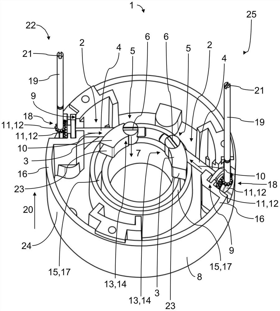
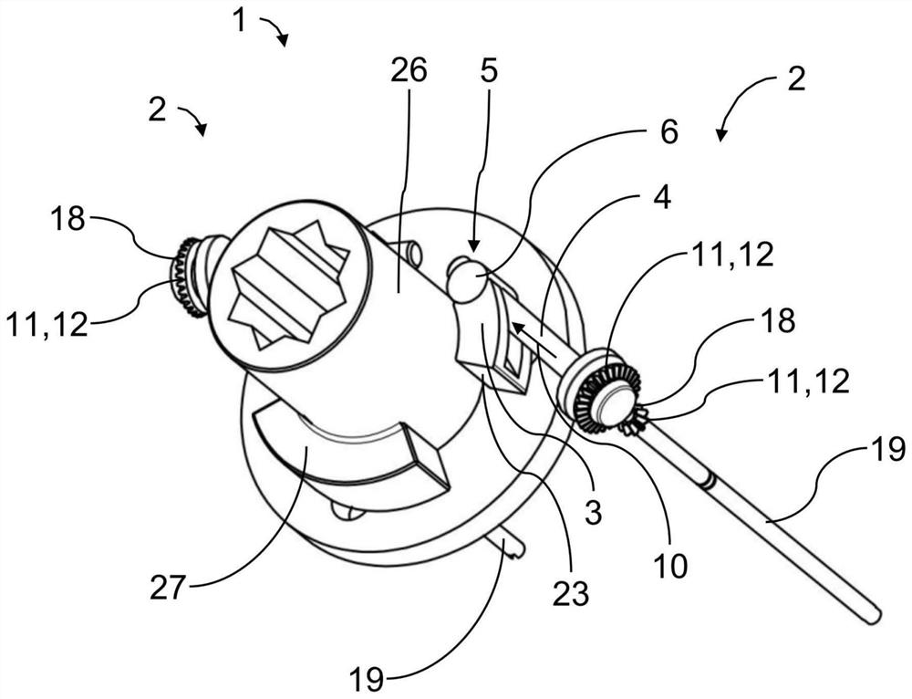
[0029]figure 1 and figure 2 An actuating drive is shown in each case, generally designated 1 , which can be used, for example, for a valve body of an actuating valve.

[0030] exist figure 1 and figure 2 The embodiment variant of the adjusting drive 1 shown in has two stop devices 2 which can each be used to adjust the position of an end stop of a component of the drive train for the adjusting drive 1 . The part can be, for example, an eccentric element 27 which is connected to the drive shaft 26 (see figure 2 ).

[0031] In this case, the end stops are respectively adjusted by the end stop elements 3 in that the position of the two end stop elements 3 is variable.

[0032] Each end stop element 3 is in each case operatively connected to the first adjusting element 4 , so that when the corresponding adjusting element 4 is actuated and / or when the adjusting element 4 is moved, the position of the associated end stop element 3 takes place. Change.

[0033] A first trans...


PUM


Abstract

An actuator (1) having two detent devices (2) which include in each case at least one terminal detent element (3) for a part (27) of a drive train, and at least one adjustment element (4, 19) which is operatively connected to the terminal detent element (3) and is specified for setting a position of the terminal detent element (3). The at least one gear unit (5, 18) is disposed between the at least one terminal detent element (3) and the at least one adjustment element (4, 19).

Description

technical field [0001] The present invention relates to an adjustment drive having at least one stop device, the at least one stop device comprising at least one end stop element for a component of the drive train and at least one end stop element connected to the end stop The stop element is an operatively connected adjustment element, which is provided for adjusting the position of the end stop element. Background technique [0002] Adjustment drives of the type mentioned at the outset are already known. Before the adjustment drive is actuated for the first time, it is usually necessary to adjust the at least one end stop element of the stop device in order to determine the position of the end stop. [0003] In the known adjusting drives, the adjusting element is usually designed as a screw, the screw head of which is arranged outside the housing. The end stop element is usually connected to an adjusting element designed as a screw. In this case, the screw is guided in ...

Claims


Application Information

Patent Timeline
Patent Type & Authority Applications(China)
IPC IPC(8): G05G5/04
CPCG05G5/04F16H2035/006F16H35/00F16K31/042F16K31/043F16K31/53
Inventor B·霍夫曼
Owner AUMA RIESTER GMBH & CO KG
Features
  • R&D
  • Intellectual Property
  • Life Sciences
  • Materials
  • Tech Scout
  • Unparalleled Data Quality
  • Higher Quality Content
  • 60% Fewer Hallucinations
Learn More