

Wireless tag system
A wireless tag and wireless communication technology, which is applied in the payment system structure, instruments, electromagnetic radiation induction, etc., can solve the problems of inability to obtain power, inability to fully receive, inability to communicate stably with wireless tags, etc., and achieve the effect of reliable power supply
- Summary
- Abstract
- Description
- Claims
- Application Information
AI Technical Summary
Problems solved by technology
Method used
Image

Examples
no. 1 approach
[0054] Hereinafter, a first embodiment in which the wireless tag system of the present invention is embodied will be described with reference to the drawings.
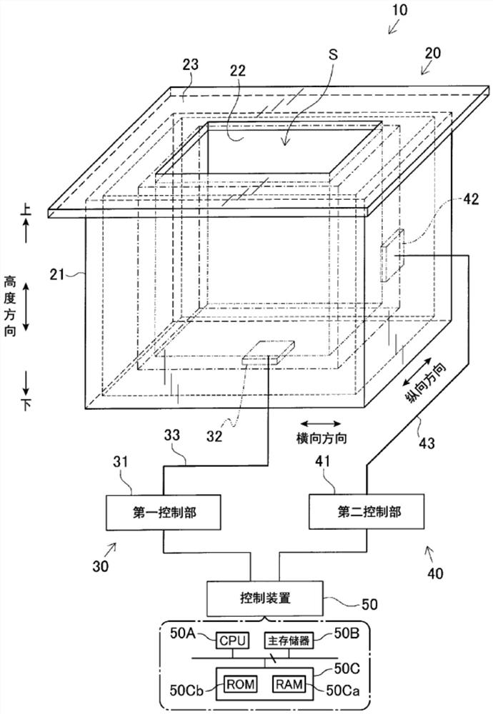
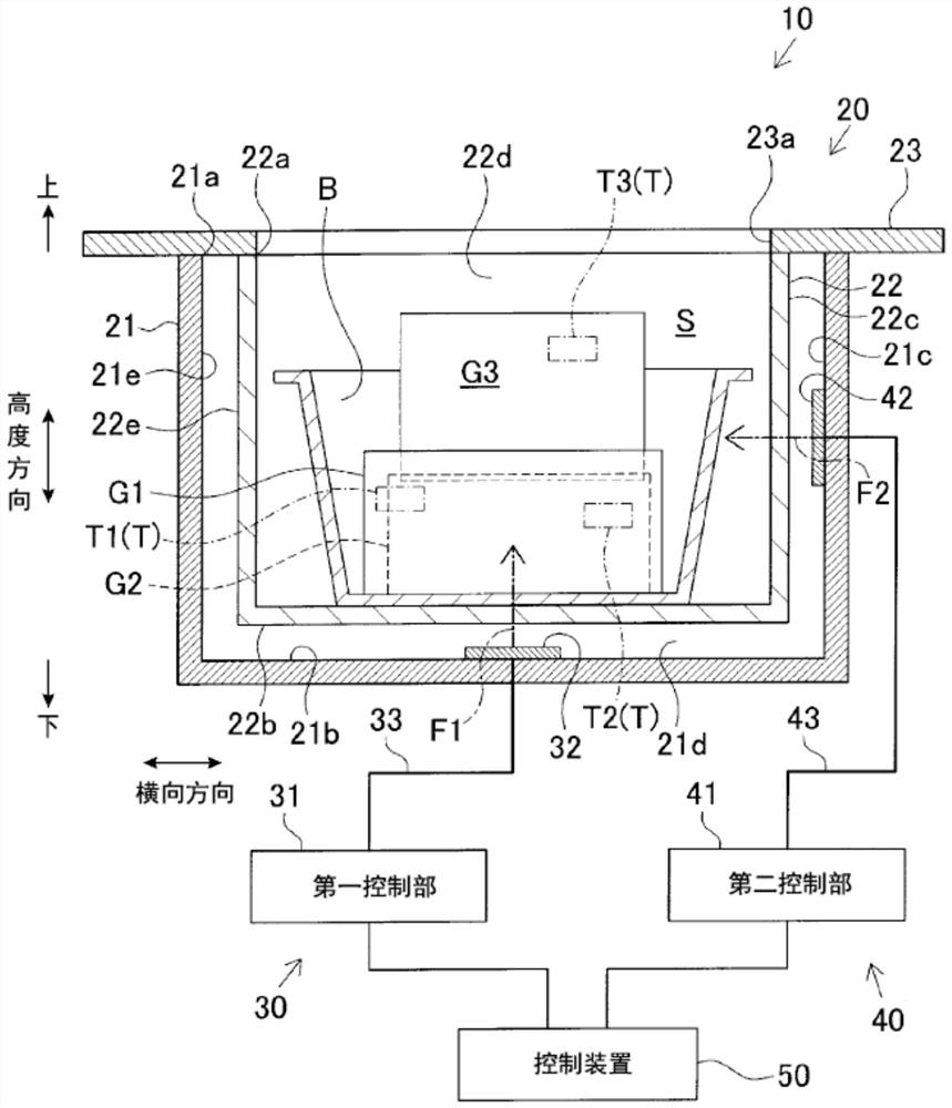
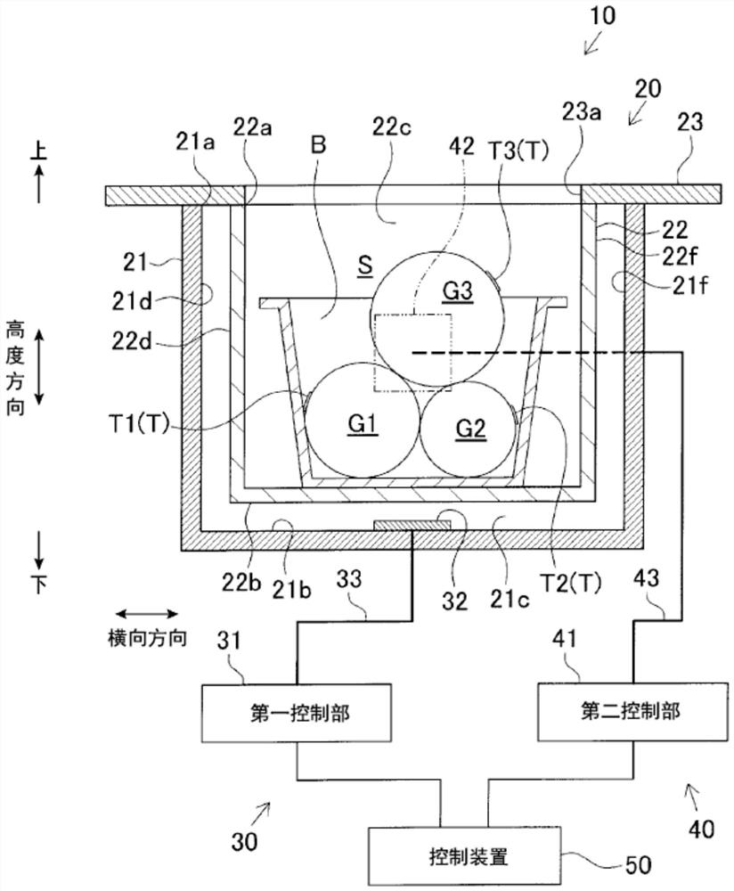
[0055] The wireless tag system 10 of the present embodiment is configured as a system including two or more wireless communication devices, and one or more wireless communication devices are arranged in a three-dimensional communication area S (predetermined communication area) such as a box containing products. More than two wireless tags (for example, passive tags) are used as wireless communication objects. Specifically, as figure 1 As shown, the wireless tag system 10 has: a storage box 20 for dividing a predetermined communication area S; two wireless communication devices (hereinafter, also referred to as the first wireless communication device 30 and the second wireless communication device 40); A control device 50 for two wireless communication devices.
[0056] In addition, a communication area collectively ...
no. 2 approach
[0086] Next, a wireless tag system according to a second embodiment of the present invention will be described with reference to the drawings.
[0087] In this second embodiment, the difference from the first embodiment described above is mainly that an unmodulated wave is transmitted from one wireless communication device as a transmission wave. Therefore, the same reference numerals are attached to the substantially same components as those of the first embodiment, and description thereof will be omitted.
[0088] The transmission wave transmitted for wireless communication with the wireless tag T is modulated to carry a signal wave, and the power supply efficiency is lower than that of an unmodulated wave in terms of power supply. Therefore, in this embodiment, in order to improve power supply efficiency easily, one wireless communication device transmits a modulated transmission wave for wireless communication, and the other wireless communication device transmits an unmod...
no. 3 approach
[0093] Next, a wireless tag system according to a third embodiment of the present invention will be described with reference to the drawings.
[0094] In this third embodiment, the main difference from the above-mentioned first embodiment is that the first wireless communication device 30 is configured as a master device, and the second wireless communication device 40 is configured as a slave device. Therefore, the same reference numerals are assigned to the components substantially the same as those of the first embodiment, and description thereof will be omitted.
[0095] In this embodiment, if Figure 6 As shown, the first wireless communication device 30 is configured as a master device, and the second wireless communication device 40 is configured as a slave device, and the above-mentioned transmission instruction is performed from the first wireless communication device 30 to the second wireless communication device 40 . That is, the transmission instruction is given f...
PUM
 Abstract
Description
Claims
Application Information