Cement road surface impressing equipment

A technology of road surface and embossing equipment, which is applied in the field of imprinting equipment, can solve problems such as complicated operation process and lack of standardization, and achieve the effect of easy device movement and convenient reuse

Active Publication Date: 2021-06-22
武汉誉城千里建工有限公司
View PDF6 Cites 1 Cited by
  • Summary
  • Abstract
  • Description
  • Claims
  • Application Information

AI Technical Summary

Problems solved by technology

[0004] In order to overcome the shortcomings of lack of standardization and complicated operation process, the technical problem to be solved: provide a cement road surface imprinting equipment that is easy to move, improves the uniformity and integrity of the imprint, and automates the operation process

Method used


Image

  • Cement road surface impressing equipment
  • Cement road surface impressing equipment
  • Cement road surface impressing equipment

Examples


Embodiment 1

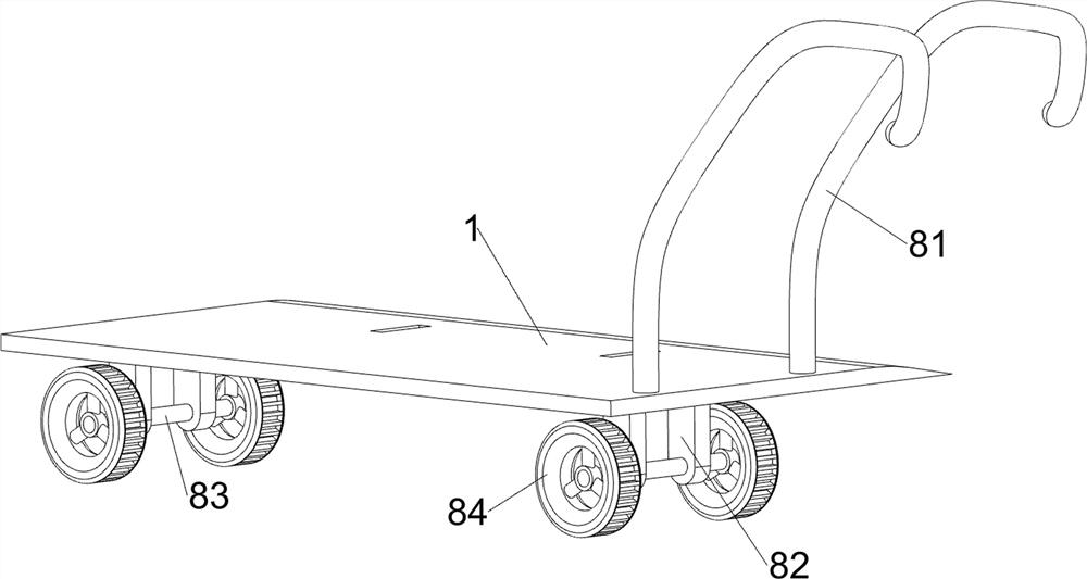
[0061] A cement road surface imprinting equipment, such as figure 1 As shown, it includes a bottom plate 1, a first pole 2, a placement plate 3, a rotating mechanism 4 and an embossing mechanism 5. Two first poles 2 are connected to the upper and lower sides of the bottom plate 1 on the left and right sides. Placement plates 3 are connected between the tops of the first support rods 2 , a rotating mechanism 4 is connected between the upper sides of the placing plates 3 , and an embossing mechanism 5 is rotatably connected to the rotating mechanism 4 .

[0062] When the device needs to be used, the user can turn the embossing mechanism 5 forward, so that the embossing mechanism 5 slides down to contact with the mold, start the rotating mechanism 4, and the rotating mechanism 4 rotates forward to drive the embossing mechanism 5 to move to the right. In order to achieve the purpose of providing driving force for the device, the rotating mechanism 4 continues to rotate forward to ...

Embodiment 2

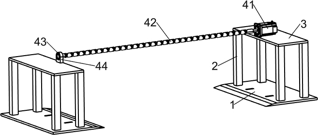
[0064] On the basis of Example 1, such as figure 2 As shown, the rotating mechanism 4 includes a servo motor 41, a twist shaft 42, a bearing 43 and a first fixed block 44, the upper side of the right placing plate 3 is connected with the servo motor 41, and the upper side of the left placing plate 3 is connected with the first fixed block. Block 44, the inner side of the first fixed block 44 is connected with a bearing 43, the output shaft of the servo motor 41 is connected with a twist shaft 42, and the twist shaft 42 is rotationally connected with the bearing 43.

[0065]When the device needs to be used, the user can turn the embossing mechanism 5 forward, so that the embossing mechanism 5 slides down to contact with the mold, start the servo motor 41, and the servo motor 41 rotates forward to drive the twist shaft 42 to move forward in the bearing 43. Rotate, the twist shaft 42 forwardly rotates to drive the embossing mechanism 5 to move to the right, to achieve the purpos...


PUM


Abstract

The invention relates to impressing equipment, in particular to cement road surface impressing equipment. The invention aims to provide the cement road surface impressing equipment which is convenient to move, improves the uniformity and integrity of impressing and has an automatic operation process. The cement road surface impressing equipment comprises bottom plates and first supporting rods, and the two sides of the top of the bottom plates on the two sides are each connected with the two first supporting rods; a placing plate which is connected between the top ends of the first supporting rods on the two sides; a rotating mechanism which is connected between the top sides of the placing plates; and a stamping mechanism which is rotationally connected to the rotating mechanism. Through cooperation of the servo motor, the twist shaft, the bearing and the first fixing block, the purpose of providing driving force for the device is achieved.

Description

technical field [0001] The invention relates to an embossing device, in particular to an embossing device for a cement road surface. Background technique [0002] At present, in the construction of cement concrete pavement, in order to meet the technical standards of friction coefficient of relevant specifications, it is necessary to form pockmarks or grooves of certain specifications on the surface of cement concrete pavement, so that the technical standard of friction coefficient of the pavement can be reached. At present, in the construction of cement concrete pavement, two methods are used to construct the pockmarked surface or groove of the pavement. One is to use a brush or steel brush to form on the surface of the concrete pavement after the cement concrete pavement is leveled and before the strength is formed. Pockmarked or grooved, another method is to use a special groove machine to form grooves on the surface of the road after the strength of the cement concrete p...

Claims


Application Information

Patent Timeline
Patent Type & Authority Applications(China)
IPC IPC(8): E01C23/08E01C23/082
CPCE01C23/08E01C23/082
Inventor 莫骏华
Owner 武汉誉城千里建工有限公司
Why Eureka
Try Eureka