Road surface warning protection frame for road construction
A protective frame and road technology, applied to roads, roads, road signs, etc., can solve the problems of safety accidents, warning frames that easily block the sight of drivers and construction workers, etc.
- Summary
- Abstract
- Description
- Claims
- Application Information
AI Technical Summary
Problems solved by technology
Method used
Image
Examples
Embodiment 1
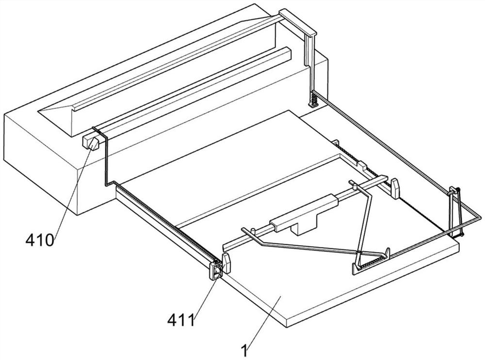
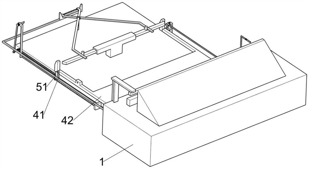
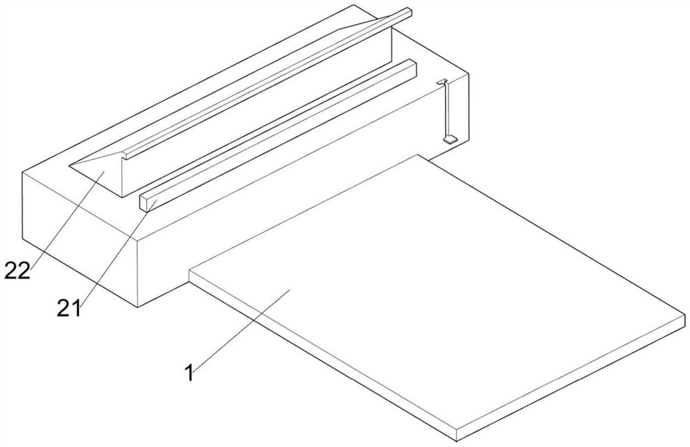
[0028] A road surface warning protective frame for road construction, such as Figure 1-8 As shown, it includes a support base 1, a deceleration limit mechanism 2, a clamping mechanism 3 and a warning mechanism 4. The support base 1 is provided with a deceleration limit mechanism 2 for decelerating the vehicle, and the clamping mechanism 3 is located on the support base 1. Above, the warning mechanism 4 for prompting the driver is also arranged on the support base 1 .
[0029] The deceleration limiting mechanism 2 comprises a limiting plate 21, an inclined-plane block 22, a buffer spring 23, a swing groove bar 24 and a first torsion spring 25, and the supporting base 1 is slidably connected with the limiting plate 21, and the limiting plate 21 is used to align the wheels. Positioning is performed so that the automobile cannot continue to move forward. The inclined-plane block 22 used for buffering the automobile wheels is also slidably connected to the support seat 1. A pair o...
Embodiment 2
[0036] On the basis of Example 1, such as Figure 9-11 Shown, also include pushing mechanism 5, and pushing mechanism 5 is located on the warning plate 42, and pushing mechanism 5 includes rotating plate 51, L-shaped bar 52, the 3rd torsion spring 53 and limit bar 54, and rotating plate 51 is fixed. Connected to one side of the warning plate 42, the L-shaped rod 52 is rotatably connected to the bottom of the rotating plate 51, the third torsion spring 53 is connected between the L-shaped rod 52 and the rotating plate 51, and the short limit rod 54 is fixed on the bottom of the L-shaped rod 54. At the bottom of the rotating plate 51 of the rod 52 , the short limiting rod 54 is in contact with the L-shaped rod 52 , and the short limiting rod 54 is used to limit the L-shaped rod 52 .
[0037] Also include reciprocating swing recording mechanism 6, reciprocating swing recording mechanism 6 is located on the support seat 1, reciprocating swing recording mechanism 6 includes movable...
PUM
 Abstract
Description
Claims
Application Information
 - R&D
- Intellectual Property
- Life Sciences
- Materials
- Tech Scout
- Unparalleled Data Quality
- Higher Quality Content
- 60% Fewer Hallucinations
Browse by: Latest US Patents, China's latest patents, Technical Efficacy Thesaurus, Application Domain, Technology Topic, Popular Technical Reports.
© 2025 PatSnap. All rights reserved.Legal|Privacy policy|Modern Slavery Act Transparency Statement|Sitemap|About US| Contact US: help@patsnap.com


