Small road surface icebreaking robot

A road surface and robot technology, which is applied in the direction of motor vehicles, snow surface cleaning, electric vehicles, etc., can solve the problems of weakening friction between wheels and road surfaces, traffic accidents, and damage to the environment, and achieves increased impact force, good impact force, Improves the effect of ice breaking effects

Inactive Publication Date: 2021-06-22
王娟
View PDF7 Cites 2 Cited by
  • Summary
  • Abstract
  • Description
  • Claims
  • Application Information

AI Technical Summary

Problems solved by technology

[0002] In some areas, the roads often freeze after rain and snow. When the roads freeze, the friction between the wheels and the road surface is greatly weakened, it is easy to slip, the car cannot be stopped, and traffic accidents are caused. The use of snow melting agents will seriously damage the environment. As a result, the green lawn is dead, so traffic accidents caused by road icing occur frequently, which brings different degrees of hidden dangers to people's travel and safety. At this time, it is necessary to use a deicing device to crush the ice on the road surface. For the convenience of clearing the ice, the deicing vehicle is a common road deicing device, but it becomes extremely inconvenient to use on some narrow roads or residential roads. The common deicing device is a large vehicle similar to a bulldozer, which directly removes ice from the ice layer. Propulsion and crushing, large equipment is difficult to use on small roads, and the applicability to narrow roads is not good. When some small deicing equipment is used on small roads, when the ice layer is thick, it is difficult for small equipment to directly treat the ice layer. Propelling and breaking, the ice breaking effect is not good

Method used


Image

  • Small road surface icebreaking robot
  • Small road surface icebreaking robot
  • Small road surface icebreaking robot

Examples


Embodiment Construction

[0038] The technical solutions in the embodiments of the present invention will be clearly and completely described below with reference to the accompanying drawings in the embodiments of the present invention. Obviously, the described embodiments are only a part of the embodiments of the present invention, but not all of the embodiments. Based on the embodiments of the present invention, all other embodiments obtained by those of ordinary skill in the art without creative efforts shall fall within the protection scope of the present invention.

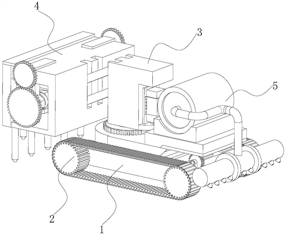
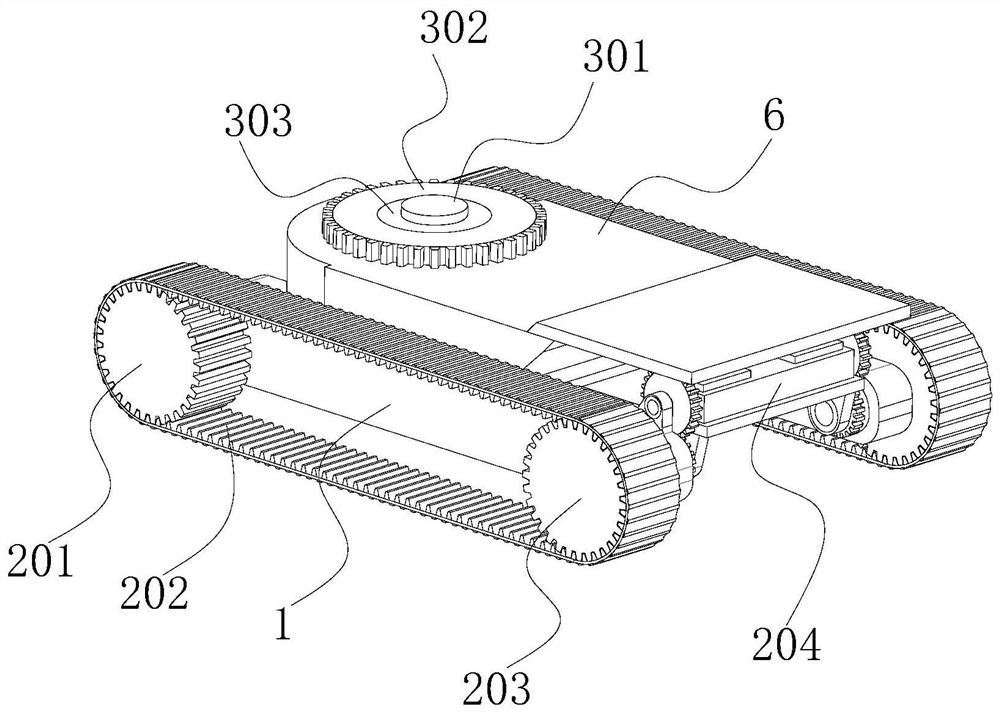
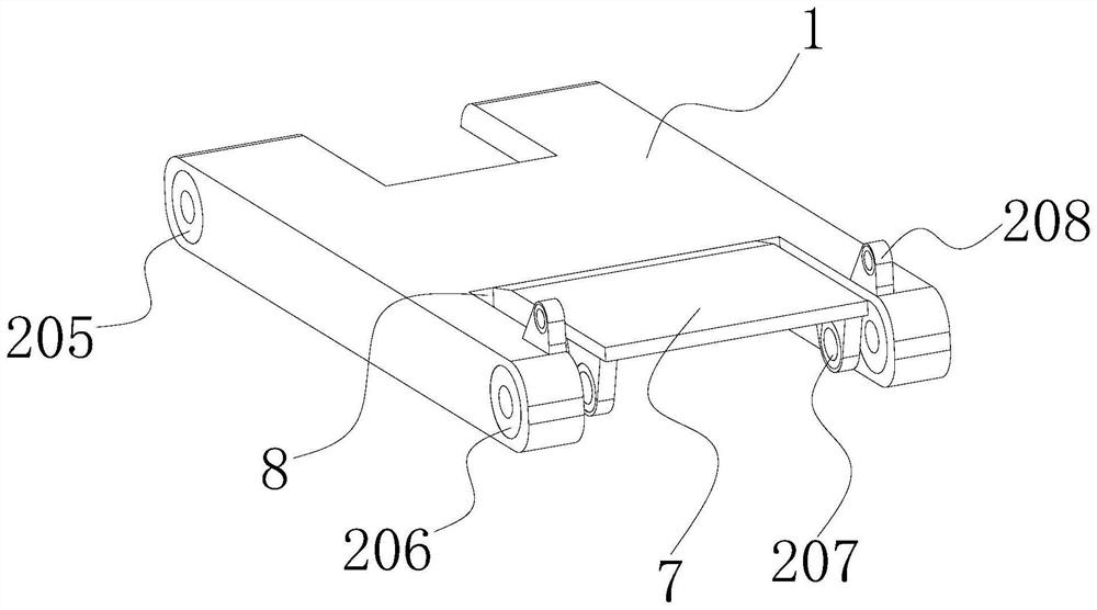
[0039] see Figure 1-14 , the present invention provides a technical solution: a small road road ice breaking robot, comprising a base frame 1, a drive mechanism 2 is installed on the outside of the base frame 1, a fixing plate 6 is fixedly installed on the upper surface of the base frame 1, and the An adjustment mechanism 3 is installed on the upper surface, an ice breaking mechanism 4 is installed on the left side of the adjustment ...


PUM


Abstract

The invention discloses a small road surface icebreaking robot, and relates to the technical field of road deicing robots, the small road surface icebreaking robot comprises a bottom frame, a driving mechanism is mounted outside the bottom frame, a fixing plate is fixedly mounted on the upper surface of the bottom frame, an adjusting mechanism is mounted on the upper surface of the fixing plate, and an icebreaking mechanism is mounted on the left side of the adjusting mechanism; and a blowing mechanism is installed on the right side of the upper surface of the underframe. According to the small road surface icebreaking robot, two fifth gears are driven by two third servo motors to rotate anticlockwise, a fixing rod drives each shifting plate to rotate clockwise, the shifting plates push impact columns and linkage plates to move upwards, make contact with springs and compress the springs in the rotating process, the shifting plates rotate to the upper portion to be separated from the linkage plates, and the linkage plates are driven by the fixing rod to rotate clockwise. And under the reset elastic force of the spring and the self-gravity of the impact column, the impact column moves downwards to impact the ice surface, so that the ice breaking effect is improved, and the problem that small ice breaking equipment cannot be pushed and broken due to the fact that an ice layer is thick during ice pushing is solved.

Description

technical field [0001] The invention relates to the technical field of road deicing robots, in particular to a small road surface ice breaking robot. Background technique [0002] In some areas, the road is often icy after rain and snow. When the road is icy, the friction between the wheels and the road is greatly weakened, and the friction between the wheels and the road is greatly weakened. As a result, the green lawn is dead, so the traffic accidents caused by road icing occur frequently, which brings different levels of hidden dangers to people's travel and safety. At this time, a deicing device is needed to crush the ice on the road surface. In order to facilitate the cleaning of ice, deicing vehicles are common road deicing devices, but it is extremely inconvenient to use in some narrow roads or residential roads. The common deicing device is a large vehicle similar to a bulldozer, which directly removes the ice. Propulsion is broken, large equipment is difficult to u...

Claims


Application Information

Patent Timeline
Patent Type & Authority Applications(China)
IPC IPC(8): E01H5/12B60K1/02B60L15/20B62D55/06
CPCE01H5/12B60K1/02B60L15/20B62D55/06Y02T10/72
Inventor 王娟
Owner 王娟
Why Eureka
Try Eureka