Positioning device of medical imaging equipment

A medical imaging and positioning device technology, which is applied in the direction of mechanical equipment, supporting machines, machine tables/supports, etc., can solve the problems of inability to adjust the vertical and horizontal positions of medical imaging equipment, increase the workload of staff, and adjust medical imaging equipment.

Inactive Publication Date: 2021-06-22
THE AFFILIATED HOSPITAL OF QINGDAO UNIV
0 Cites 0 Cited by

AI-Extracted Technical Summary

Problems solved by technology

[0003] The current positioning device of medical imaging equipment needs to manually adjust the position of the medical imaging equipment during use, and cannot automatically adjust the vertical and horizontal positions of the medical imaging equipment, which increases the workload of t...

Method used

Described fine-tuning assembly comprises installation channel plate 18, the 3rd leading screw 19, the 3rd motor 20 and moving block 21, and described connecting block 17 bottoms are fixedly installed with installation channel plate 18, and described installation channel plate 18 is below A C-shaped plate with an opening, a third lead screw 19 is horizontally arranged on the inner side of the installation groove plate 18, and one end of the third lead screw 19 passes through the installation groove plate 18 and is fixedly connected with the third motor 20, and the third lead screw 19 The outer thread of the rod 19 is connected with a moving block 21. The bottom of the moving block 21 is connected to the top of the medical imaging device 22. When the third motor 20 is working in the forward direction, the third lead screw 19 rotates clockwise, and the moving block 21 is left. to drive the medical imaging equipment 22 to move to the left, when the third motor 20 works in reverse, the third lead screw 19 rotates counterclockwise, the moving block 21 moves to the right, and drives the medical imaging equipment 22 to move to the right, by controlling the third The forward and reverse rotation of the motor 20 can fine-tune the horizontal position of the medical imaging device 22 from left to right, improving the practicability of the device.
Different fr...

Abstract

The invention discloses a positioning device of medical imaging equipment, belongs to the technical field of medical equipment, and solves the problem that the positioning device of the medical imaging equipment in the prior art cannot automatically adjust the longitudinal and transverse positions of the medical imaging equipment. According to the technical scheme, the positioning device comprises a movable seat, and a support is vertically welded at the upper portion of the movable seat; a lifting plate is arranged on the outer side of the support, the upper portion of the movable seat is connected with the lifting plate through a lifting assembly, a connecting box is welded to one side wall of the lifting plate, a horizontal position adjusting assembly is arranged in the connecting box, and a connecting block is fixedly installed on one side of the horizontal position adjusting assembly; and the bottom of the connecting block is connected with the medical imaging equipment through a fine adjustment assembly. The positioning device of the medical imaging equipment has the advantages that the height can be adjusted and fixed, the horizontal displacement can be adjusted, the horizontal fine adjustment can be realized, and the positioning device is simple, convenient and practical.

Application Domain

Stands/trestles

Technology Topic

Medical imagingMedical physics +4

Image

  • Positioning device of medical imaging equipment
  • Positioning device of medical imaging equipment
  • Positioning device of medical imaging equipment

Examples

  • Experimental program(2)

Example Embodiment

[0028] Example 1
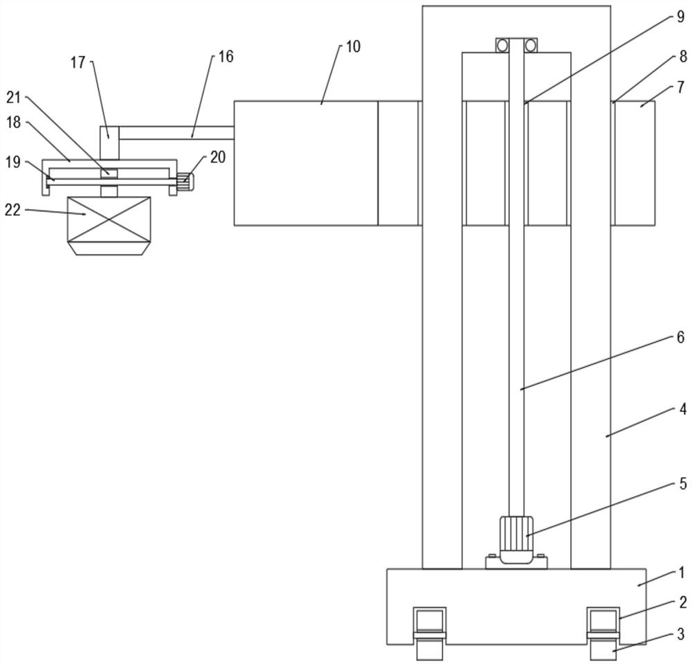
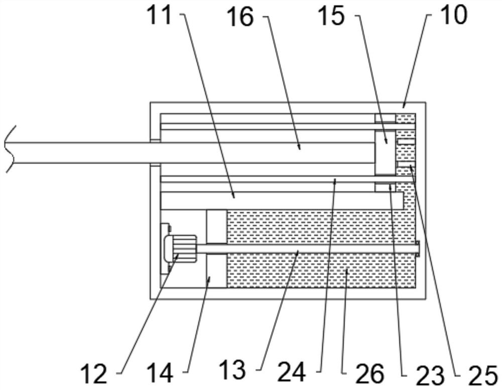
[0029] see Figure 1 ~ Figure 3 , a positioning device for medical imaging equipment, comprising a moving base 1, a bracket 4 is vertically welded on the upper part of the moving base 1, a lifting plate 7 is arranged on the outside of the bracket 4, and the upper part of the moving base 1 passes through a lifting assembly and a lifting plate 7, the side wall of the lifting plate 7 is welded with a connection box 10, the inside of the connection box 10 is provided with a horizontal position adjustment assembly, and a connection block 17 is fixedly installed on one side of the horizontal position adjustment assembly, and the connection block The bottom of the 17 is connected with the medical imaging device 22 through a fine-tuning assembly.
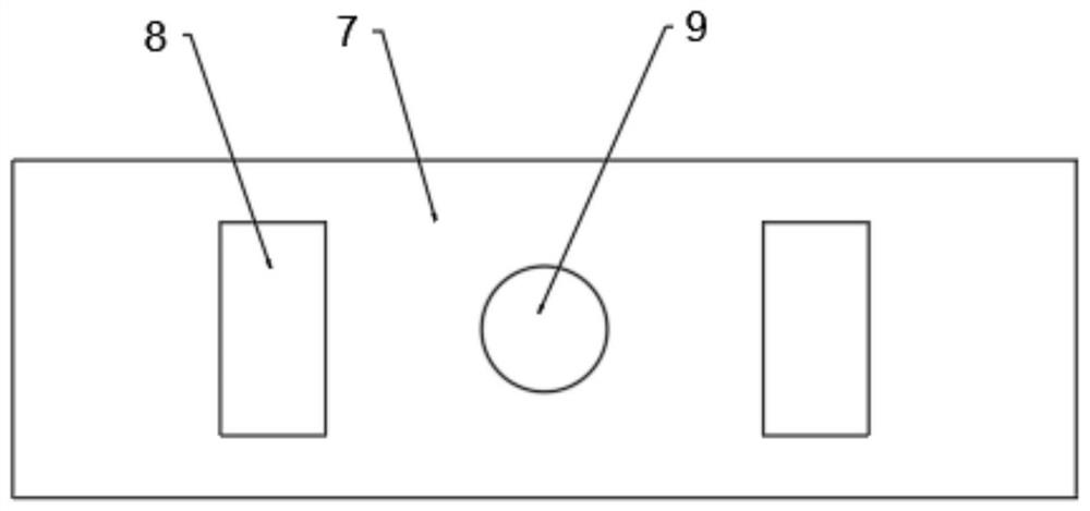
[0030] The lifting assembly includes a first motor 5, a first leading screw 6, a through hole 8 and a threaded hole 9, the upper part of the moving seat 1 in the middle of the support 4 is fixedly installed with a first motor 5, and the output of the first motor 5 The end is fixedly connected with the first lead screw 6, the top of the first lead screw 6 is connected to the top of the bracket 4 in rotation, the two sides of the lifting plate 7 are symmetrically provided with through holes 8, and the middle part of the lifting plate 7 is provided with threaded holes. 9. The lifting plate 7 is slidably connected to the bracket 4 through the through hole 8, and the lifting plate 7 is screwed to the first lead screw 6 through the threaded hole 9. When the first motor 5 works in the forward direction, the first lead screw 6 moves forward Clockwise rotation can drive the lifting plate 7 to move upward, which can realize the rise of the height of the medical imaging equipment 22. When the first motor 5 works in reverse, the first lead screw 6 rotates counterclockwise, which can drive the lifting plate 7 to move downward, which can realize The height reduction of the medical imaging equipment 22 can flexibly adjust the height of the medical imaging equipment 22 .
[0031] The horizontal position adjustment assembly includes a partition plate 11, a second motor 12, a second lead screw 13, a threaded plate 14, a moving plate 15, a cross bar 16, a limit post 25 and hydraulic oil 26, and the middle part of the inside of the connection box 10 A partition 11 is fixedly arranged horizontally, and a gap is provided between the partition 11 and the inner wall of the connection box 10, and a second motor 12 is fixedly installed on the inner wall of the connection box 10 below the partition 11, and the second The output end of the motor 12 is fixedly connected with a second lead screw 13, and the outer side of the second lead screw 13 is threaded with a threaded plate 14, and the threaded plate 14 is closely attached to the bottom of the partition plate 11 and the inner wall of the connection box 10 Setting, the upper part of the partition 11 and the inner wall of the connection box 10 are closely fitted and slidably provided with a moving plate 15, and the connection box 10 is symmetrically and horizontally welded with a limiting column 25 near the moving plate 15, and the limiting column 25 The length is greater than the length of the gap between the partition 11 and the connection box 10, and the middle part of one side of the moving plate 15 is horizontally welded with a cross bar 16, and the outer end of the cross bar 16 is fixedly connected with the connecting block 17, and the threaded plate 14 The inner space of the connection box 10 on the side away from the second motor 12 and the side of the moving plate 15 away from the cross bar 16 is filled with hydraulic oil 26, the second motor 12 works forward, and the second lead screw 13 rotates clockwise , the threaded plate 14 moves away from the second motor 12, pushes the hydraulic oil 26 to move upward, pushes the moving plate 15 away from the limit post 25, drives the cross bar 16 to move, and can adjust the horizontal position of the medical imaging device 22, Through the limit post 25 , it is possible to prevent the moving plate 15 from contacting the side wall of the connection box 10 above the gap and affecting the upward movement of the hydraulic oil.
[0032] The fine-tuning assembly includes a mounting groove plate 18, a third lead screw 19, a third motor 20 and a moving block 21. The bottom of the connecting block 17 is fixedly equipped with an installation groove plate 18, and the installation groove plate 18 is a C with an opening below. template, the inner side of the installation groove plate 18 is horizontally provided with a third lead screw 19, one end of the third lead screw 19 passes through the installation groove plate 18 and is fixedly connected with the third motor 20, and the outside of the third lead screw 19 The thread sleeve is connected with a moving block 21, and the bottom of the moving block 21 is connected with the top of the medical imaging device 22. When the third motor 20 works in the forward direction, the third lead screw 19 rotates clockwise, and the moving block 21 moves to the left, driving The medical imaging device 22 moves to the left. When the third motor 20 works in reverse, the third lead screw 19 rotates counterclockwise, and the moving block 21 moves to the right, driving the medical imaging device 22 to move to the right. By controlling the third motor 20 Forward and reverse, the horizontal position of the medical imaging device 22 can be fine-tuned left and right to improve the practicability of the device.
[0033] The bottom of the moving seat 1 is symmetrically provided with moving grooves 2, and rollers 3 are rotated in the moving grooves 2, and the position of the device is conveniently moved through the rollers 3.
[0034]Preferably, in this embodiment, the bracket 4 is a C-shaped bracket with an opening at the bottom.
[0035] Preferably, in this embodiment, the moving plate 15 is vertically symmetrically provided with guide holes 23 , and guide rods 24 are slidably arranged inside the guide holes 23 , and the guide rods 24 are horizontally and fixedly installed inside the connection box 10 .

Example Embodiment

[0036] Example 2
[0037] see Figure 1 ~ Figure 4 , as a positioning device for medical imaging equipment in Example 1, including a moving base 1, a bracket 4 is vertically welded on the upper part of the moving base 1, and a lifting plate 7 is provided on the outside of the bracket 4, and the upper part of the moving base 1 Connected with the lifting plate 7 through the lifting assembly, the side wall of the lifting plate 7 is welded with a connection box 10, the inside of the connection box 10 is provided with a horizontal position adjustment assembly, and a connection block is fixedly installed on one side of the horizontal position adjustment assembly 17. The bottom of the connecting block 17 is connected to the medical imaging device 22 through a fine-tuning assembly.
[0038] Different from Embodiment 1, the inside of the lifting plate 7 is symmetrically provided with a fixing groove 27, and a positioning assembly is arranged in the fixing groove 27, and the positioning assembly includes an electric telescopic rod 28, a vertical plate 29, a fixing rod 30 and Fixed hole 31, electric telescopic rod 28 is horizontally installed on the inner wall of described fixed groove 27, and one end of described electric telescopic rod 28 is fixedly connected with one side of vertical plate 29, and the other side of described vertical plate 29 is horizontally welded with Fixed rod 30, several fixed holes 31 are evenly arranged on the outer wall of the support 4, and the fixed rod 30 and the fixed holes 31 cooperate with each other. When the lifting plate 7 rises to a certain height, the first motor 5 stops working, and the motor The telescopic rod 28 is extended outward, and the vertical plate 29 pushes the fixed rod 30 to cooperate with the fixed hole 31 to realize the fixing of the height of the lifting plate 7 and improve the stability of the height of the medical imaging device 22 during work.
[0039] The rest of the structure of this embodiment is the same as that of Embodiment 1.
[0040] The working principle of the present invention is:
[0041] When the first motor 5 works in the forward direction, the first lead screw 6 rotates clockwise, which can drive the lifting plate 7 to move upward, which can realize the rise of the height of the medical imaging equipment 22. When the first motor 5 works in the reverse direction, the first lead screw 6 Rotating counterclockwise can drive the lifting plate 7 to move downward, which can realize the decline of the height of the medical imaging equipment 22, and can flexibly adjust the height of the medical imaging equipment 22; the second motor 12 works forward, and the second lead screw 13 rotates clockwise. The threaded plate 14 moves away from the second motor 12, pushes the hydraulic oil 26 to move upward, pushes the moving plate 15 away from the limit post 25, drives the cross bar 16 to move, and can adjust the horizontal position of the medical imaging device 22; The third motor 20 works in the forward direction, the third lead screw 19 rotates clockwise, the moving block 21 moves to the left, and drives the medical imaging equipment 22 to move to the left, when the third motor 20 works in the reverse direction, the third lead screw 19 rotates counterclockwise , the moving block 21 moves to the right, driving the medical imaging equipment 22 to move to the right; when the lifting plate 7 rises to a certain height, the first motor 5 stops working, the electric telescopic rod 28 extends outward, and the vertical plate 29 pushes the fixed rod 30 cooperates with the fixing hole 31 to realize the fixing of the height of the lifting plate 7 and improve the stability of the height of the medical imaging device 22 in the working process.

PUM

no PUM

Description & Claims & Application Information

We can also present the details of the Description, Claims and Application information to help users get a comprehensive understanding of the technical details of the patent, such as background art, summary of invention, brief description of drawings, description of embodiments, and other original content. On the other hand, users can also determine the specific scope of protection of the technology through the list of claims; as well as understand the changes in the life cycle of the technology with the presentation of the patent timeline. Login to view more.
Why Eureka
Try Eureka