Rigidity measuring and calculating method for hollow floor with built-in corrugated cylinders

A hollow floor, corrugated technology, applied in the direction of calculation, special data processing applications, instruments, etc., can solve the problems of lack of simultaneous consideration, incomplete development of structural internal force calculation formulas, and incomplete theoretical results, and achieves detailed theoretical research. , The effect of force performance science

Active Publication Date: 2021-06-22
QUZHOU UNIV
View PDF6 Cites 1 Cited by
  • Summary
  • Abstract
  • Description
  • Claims
  • Application Information

AI Technical Summary

Problems solved by technology

[0003] In 2004, my country promulgated the technical regulations on hollow floors "Technical Regulations on Cast-in-situ Concrete Hollow Floor Structures". In terms of theoretical research on the mechanical properties of hollow floors, cast-in-place concrete hollow floors in high-rise buildings face many theoretical problems such as stiffness, such as the incomplete development of formulas for the calculation of structural internal forces of various types of hollow floors, theoretical The result is not yet perfect
[0011] To sum up, in the current theoretical research on floors, the built-in corrugated pipe floor is a new type of floor. At present, there are few theoretical studies involved, and there is no simultaneous consideration of reinforced concrete slabs, ribbed slabs, and corrugated floors. Theoretical formulations of stiffness for three material properties and construction properties of tubes

Method used


Image

  • Rigidity measuring and calculating method for hollow floor with built-in corrugated cylinders
  • Rigidity measuring and calculating method for hollow floor with built-in corrugated cylinders
  • Rigidity measuring and calculating method for hollow floor with built-in corrugated cylinders

Examples


Embodiment

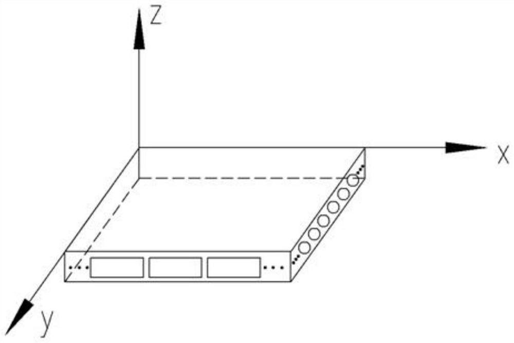
[0070] Built-in corrugated cylindrical hollow floor cover stiffness measuring method, combined with thin wall corrugated cylinders, the structural characteristics of concrete hollow cover, introduced into the Cartesian coordinate system, establish hollow floor coordinates figure 1 As shown, Oz is above the OXY coordinate plane, assuming that Y is parallel to the tube axis direction, and X is perpendicular to the tube axial direction.

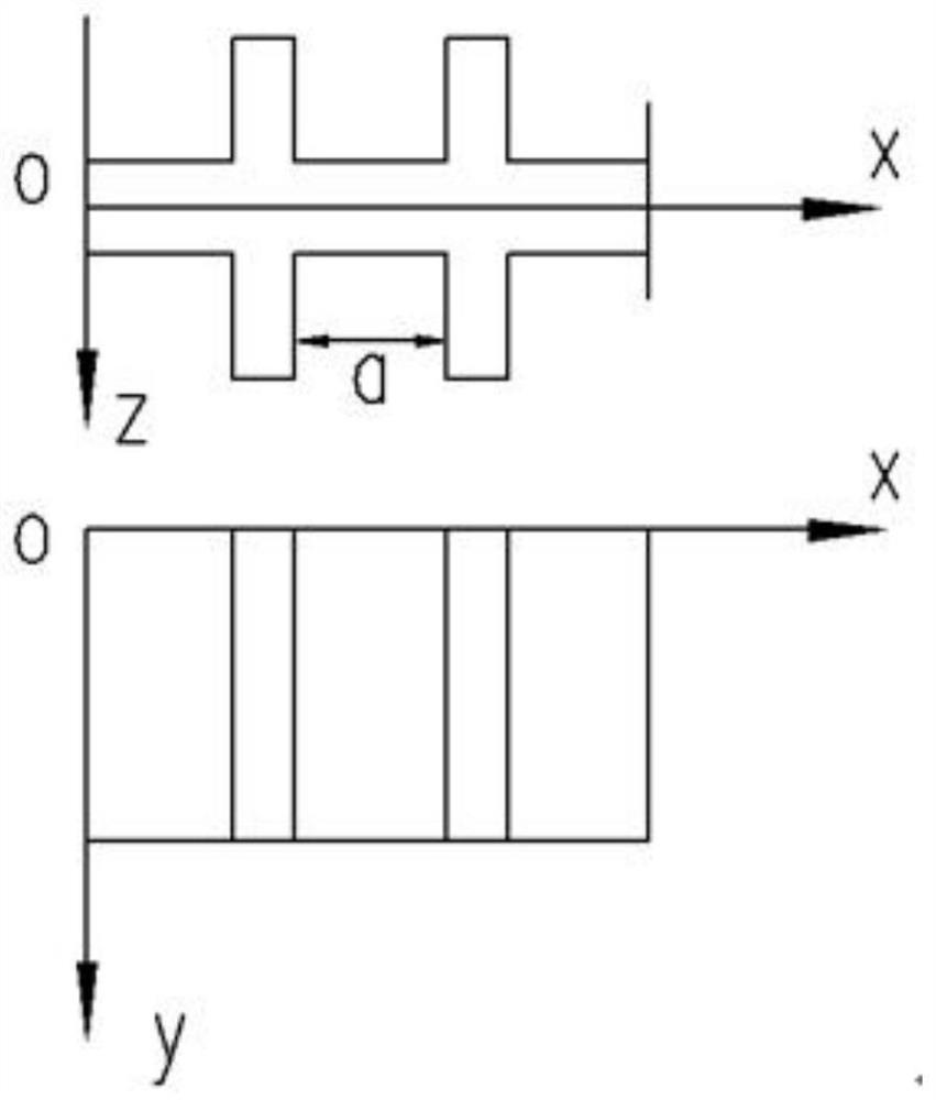
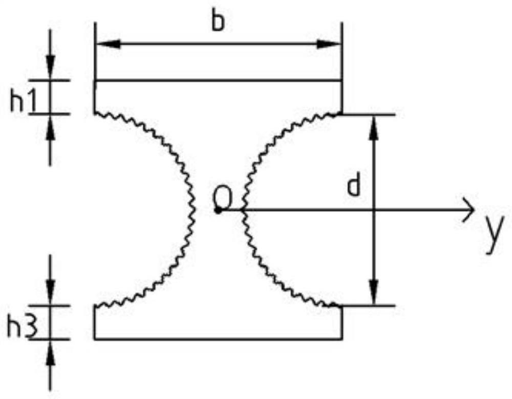
[0071] The web part is regarded as a rib into the wing edge, figure 2 For the use of ribbed

[0072] Schematic, formula (3.1) is a rigidity theoretical formula

[0073]

[0074] In the formula, e is the concrete elastic modulus, E 'is the elastic modulus of the rib, and the spacing of the ribs, and I' is the cross-sectional moment of the rib, and μ is the Poisson ratio of concrete, δ is a plate thickness.

[0075] The X-direction and y direction of the built-in thin-walled corrugated cylindrical hollow floor can be constructed as a plurality of eq...


PUM


Abstract

The invention discloses a rigidity measuring and calculating method for hollow floor with built-in corrugated cylinders, which combines the material and construction characteristics of a reinforced concrete plate, a ribbed plate and a corrugated pipe, and comprises the following steps: S1, combining the structural characteristics of a corrugated cylinder cast-in-place concrete hollow floor, introducing a Cartesian coordinate system, and establishing a hollow floor coordinate graph; s2, adopting the principle of equivalent stiffness, considering orthotropic anisotropy and material anisotropy at the same time, introducing a corrugation simplification coefficient, improving stiffness formulas of ribbed plates and corrugated plates in elastic mechanics, and providing a stiffness formula of the improved corrugated pipe hollow floor system; s3, taking that the X direction and the Y direction of the built-in thin-wall corrugated cylinder hollow floor are composed of a plurality of equidistant sections, and taking one unit section on each axis for analysis; s4, calculating the flexural rigidity of the plate parallel to the pipe axis direction; s5, calculating the flexural rigidity of the plate in the direction perpendicular to the pipe axis; and S6, calculating the section stiffness of the hollow floor. The invention enriches and perfects the existing calculation mode, and is an innovation of the existing rigidity research theory.

Description

Technical field [0001] The present invention relates to the field of architectural tests, in particular, to a built-in ripple cylinder hollow floor cover stiffness measurement method. Background technique [0002] In order to adapt to the development trend of today's construction industry, enhance people's quality of life, respond to national development of green energy-saving and environmental policies, the development of cash-in-in-situ concrete hollow covers is not only a new innovation in China, but also for my country's economic value system It played the role of promoting. [0003] In 2004, my country released the technical procedures of the associated hollow cover "Cast-situ Concrete Hollow House Structure Technology", although the hollow coverings are extremely significant for my country's hollow cover, both structural design or construction technology, but In terms of theoretical research of mechanical properties such as hollow floor, the currently-in-place concrete holl...

Claims


Application Information

Patent Timeline
Patent Type & Authority Applications(China)
IPC IPC(8): G06F30/23G06Q50/08G06F119/14
CPCG06F30/23G06Q50/08G06F2119/14Y02T90/00
Inventor 刘军杨凤苗玉洁黄艳辉游赵谢伟亮祝康毅雷进杰
Owner QUZHOU UNIV
Why Eureka
Try Eureka