Telescopic detection device and method based on space optical communication

A technology for space optical communication and detection equipment, applied in the field of detection, can solve the problems of poor anti-interference ability, increased operation difficulty of cables, slow shrinkage speed, etc. interference, the effect of ensuring successful transmission

Active Publication Date: 2022-07-29
北京方鸿智能科技有限公司
View PDF3 Cites 0 Cited by
  • Summary
  • Abstract
  • Description
  • Claims
  • Application Information

AI Technical Summary

Problems solved by technology

For the wired design, due to the use of spring signal wires, the telescopic distance is small and the shrinkage speed is slow, otherwise the spring signal wires will be curled and stuck, and the inner ends of each pipe joint are likely to scratch with the spring signal wires, resulting in cable failure. damage
Moreover, the signal line is directly routed externally, the appearance is not clean, and it is easy to be hooked by foreign objects. The redundant cables need to be tightened by the operator at all times, which increases the difficulty of operation.
[0005] For wireless design, the existing radio wave communication methods such as WiFi, Bluetooth and Zigbee have poor anti-interference ability, poor confidentiality, poor electronic countermeasure ability, and high risk of use, especially in fields with high anti-interference and confidentiality requirements.

Method used


Image

  • Telescopic detection device and method based on space optical communication
  • Telescopic detection device and method based on space optical communication
  • Telescopic detection device and method based on space optical communication

Examples


Embodiment Construction

[0028] The present disclosure will be described more fully hereinafter with reference to the accompanying drawings, in which exemplary embodiments of the disclosure are shown. However, the present disclosure may be practiced in different embodiments and should not be construed as limited to the embodiments described herein. These embodiments are provided so that this disclosure will be thorough and complete, and will fully convey the scope of the disclosure to those skilled in the art. In the drawings, the thicknesses and regions of layers may be exaggerated for clarity. Throughout the specification, the same reference numerals are used to refer to the same elements. The elements may have different interrelationships and different positions for different implementations.

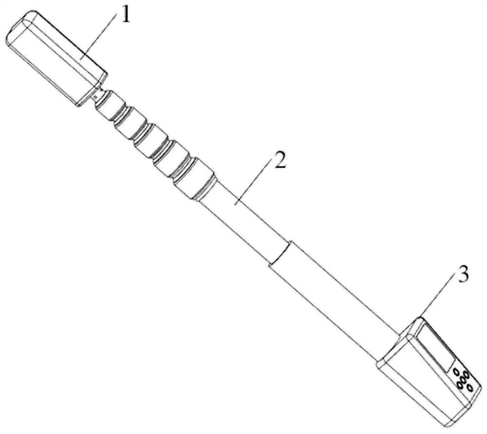
[0029] figure 1 It is a schematic diagram of a telescopic detection device based on spatial optical communication according to an exemplary embodiment of the present application. like figure 1 As shown,...


PUM


Abstract

Disclosed are a telescopic detection device and method based on space optical communication. The detection device includes: a detection unit for detecting a space signal and processing the detection result into an optical signal for output; a host unit for receiving a signal sent by the detection unit and obtain the detection result; the telescopic unit, which is hollow, is connected to the detection unit and the host unit, and is used for optical communication between the detection unit and the host unit. The telescopic detection device of the present application can not only achieve compactness, beauty and operability of the device, but also have strong security and confidentiality, and can not only avoid being blocked by foreign objects and disturbed by external light, regardless of whether the device is shaken or not. Bending, can ensure the successful transmission of data.

Description

technical field [0001] The present disclosure relates to the field of detection technology, and more particularly, to a telescopic detection device and method based on spatial optical communication. Background technique [0002] The background description provided herein is for the purpose of generally presenting the context of the disclosure. To the extent described in this Background section, the work of the currently named inventors, and aspects of the description that may not have constituted prior art at the time of filing, are neither expressly nor impliedly considered to be prior art with respect to the present disclosure. technology. [0003] The telescopic detection device in the prior art is mainly composed of a detection unit, a telescopic unit and a host unit. The function of the telescopic unit is to increase the detection distance. The specific implementation method is as follows: the detection unit is fixed on the top of the telescopic unit, and each tube se...

Claims


Application Information

Patent Timeline
Patent Type & Authority Patents(China)
IPC IPC(8): H04B10/079H04B10/11
CPCH04B10/079H04B10/11
Inventor 张阳天涂德海乐爱兵薛斌刘维娟薛薇
Owner 北京方鸿智能科技有限公司
Why Eureka
Try Eureka