Rotary flow pulsation generating device

A flow pulsation and generation device technology, applied in mechanical equipment, circuit components, etc., can solve the problems of large flow pulsation, large axial force, dense arrangement of through holes, etc. in the pipeline system, and achieve excellent dynamic balance characteristics. The effect of small force and easy installation

Inactive Publication Date: 2021-06-25
HARBIN ENG UNIV
View PDF12 Cites 0 Cited by
  • Summary
  • Abstract
  • Description
  • Claims
  • Application Information

AI Technical Summary

Problems solved by technology

However, the dense arrangement and small size of the through holes on the wheel disc result in a small flow pulsation amplitude and large axial force, which cannot meet the continuous large flow pulsation requirements of the pipeline system.

Method used


Image

  • Rotary flow pulsation generating device
  • Rotary flow pulsation generating device
  • Rotary flow pulsation generating device

Examples


Embodiment Construction

[0016] The present invention is described in more detail below in conjunction with accompanying drawing example:

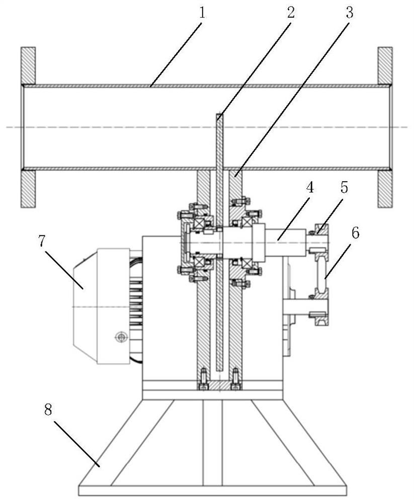
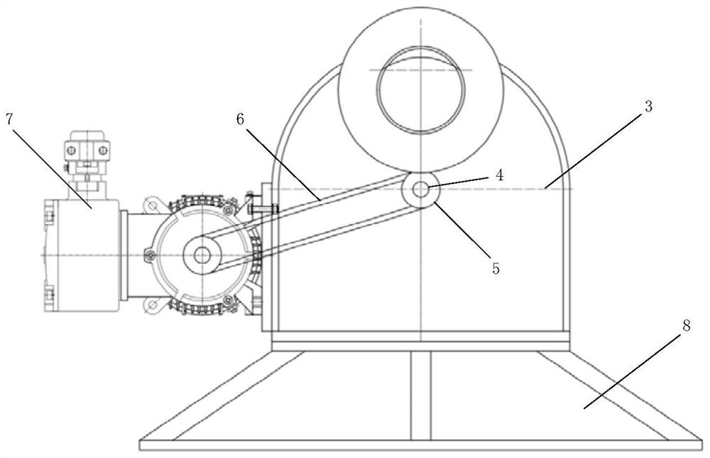
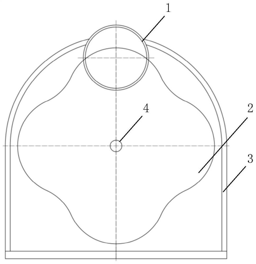
[0017] combine Figure 1-5 , The present invention provides a rotary flow pulsation excitation device with adjustable frequency and amplitude, which includes a pipe section 1, an overcurrent baffle 2, a casing 3, a shaft 4, a pulley 5, a belt 6, a motor 7 and a base 8. The overflow baffle 2 is inserted horizontally into the pipe section 1, and the drive shaft 4 is connected to the overflow baffle 2 by pins. The housing 3 installed outside the overflow baffle 2 acts as a seal, and the drive shaft 4 and the motor 7 pass through the belt 6 Connect with the pulley 5 to ensure that the motor 7 and the drive shaft 4 rotate at the same speed. The whole set of devices is fixed on the base 8, and the base 8 is connected with the ground through anchor bolts. When the motor 7 rotates with the drive shaft 4 and the overflow baffle 2, the flow area of ​​the pipe section 1 cha...


PUM


Abstract

The invention aims to provide a rotary flow pulsation generating device. The device comprises a pipe section, an overflowing baffle, a motor and a shell, a transmission shaft is connected with a first belt pulley, a motor shaft of the motor is connected with a second belt pulley, the first belt pulley and the second belt pulley are connected through a belt, and the overflowing baffle is installed outside the transmission shaft and fixed to the transmission shaft. The shell is installed at the outer side of the overflowing baffle and fixed to the pipe section, a radial opening is formed in the pipe section in the radial direction of the pipe section, the overflowing baffle extends into the radial opening, the shell is fixed to the base, and the base is fixed to the ground. The overflowing baffle does not completely block the overflowing area of a pipeline in the rotating process, continuous flow pulsation can be generated, and the function of adjusting the flow fluctuation frequency and amplitude can be achieved by adjusting the rotating speed of the motor, the size of the overflowing baffle and the opening degree of a flow adjusting valve. The flow pulsation device has the advantages of being excellent in dynamic balance characteristic, small in axial force and compact in structure, and a pipeline connector is convenient to install.

Description

technical field [0001] The invention relates to a test device for fluid mechanical acoustic structures such as pumps and valves, in particular to a dynamic characteristic test of fluid mechanical acoustic structures such as pumps and valves. Background technique [0002] The pipeline system includes components such as pumps, valves, and pipelines. All components work together to ensure the safe, stable, efficient and economical operation of the entire set of equipment. The operating point of the pipeline system is determined by the head performance curve of the pump and the pipeline impedance characteristic curve (including valves and pipelines). When the system adjusts the flow rate, the shape and position of the pump performance curve and the pipeline characteristic curve change, resulting in a change in the operating point of the system. The system is unstable. The flow adjustment methods of the pipeline system are mainly divided into throttling adjustment and variable ...

Claims


Application Information

Patent Timeline
Patent Type & Authority Applications(China)
IPC IPC(8): F15C3/16
CPCF15C3/16
Inventor 李玩幽简洁王东华率志君郭宜斌姜晨醒张相元孟长霖
Owner HARBIN ENG UNIV
Why Eureka
Try Eureka