Power transmission device with combined pericycloid mechanism and double-crank mechanisms

A double-crank mechanism and power transmission technology, which is applied in the direction of machines/engines, mechanical equipment, combustion engines, etc., can solve the problems of complex shape, difficult implementation, and difficult processing, etc., and achieve a small number of parts, simple structure, and design The effect of many parameters

Inactive Publication Date: 2013-04-24
NAT UNIV OF DEFENSE TECH
View PDF3 Cites 0 Cited by
  • Summary
  • Abstract
  • Description
  • Claims
  • Application Information

AI Technical Summary

Problems solved by technology

Although these studies have improved the power performance of the reciprocating piston engine to a certain extent, they have not fundamentally changed the current situation of low power density of the engine due to the inherent defects of the power transmission part.
The successful development and application of the rotary piston engine is the triangular rotor rotary piston engine invented by German Wankel in 1957. This engine has relatively high power density and promising application prospects, but the manufacturing cost is high due to the complicated shape of the rotor. , and there are difficult problems such as difficult sealing, poor power performance at low speed, poor fuel economy, etc., so that the theoretical superiority of the rotary piston engine has not been fully utilized so far.
[0004] The lower power density not only restricts the further improvement of the performance of the piston engine, but also limits the application of the piston engine in many occasions
The above two types of piston engines are limited by the inherent defects of the power transmission part, and the power density is difficult to reach 1 (Kw / Kg)
The low power density of power sources has become a bottleneck in the development of some equipment technologies
[0005] In order to improve the characteristics of traditional piston engines, various solutions have been proposed, among which the dual-rotor piston engine is a very popular research direction. Over the years, a large number of researches have been carried out at home and abroad. breakthroughs have been made, but there are two problems in the existing double-rotor piston engine research that are difficult to solve
[0006] First, the differential drive assembly that constrains the motion of the rotor is complex
In the literature that has been found, some people use difficult-to-machine parts such as oval gears, transmission gears, non-circular gears, and oval gears to realize differential drive rotors. These solutions are not only high in cost, but also poor in reliability, especially for When the high power density of the engine is required to perform more work per revolution of the power shaft, the shape of these special parts will become very complicated and the processing will be too difficult; others use unconventional parts such as one-way devices, ratchets, and springs. To achieve differential drive rotors, as we all know, these components do not have practical value when used as parts for engine power transmission, and there will be great impact when the rotor rotates at a non-uniform speed, and the running noise is very loud; some people also use gears, Conventional components such as connecting rods realize differential drive rotors, but some of the mechanism schemes are too complicated, not reliable enough, and difficult to implement, and some have a large number of parts and are not compact in structure
Secondly, it is difficult to achieve more than 10 times of work per revolution of the rotor, which cannot guarantee the high power density of the engine

Method used


Image

  • Power transmission device with combined pericycloid mechanism and double-crank mechanisms
  • Power transmission device with combined pericycloid mechanism and double-crank mechanisms
  • Power transmission device with combined pericycloid mechanism and double-crank mechanisms

Examples


Embodiment Construction

[0022] The present invention will be further described in detail below with reference to the accompanying drawings and specific embodiments.

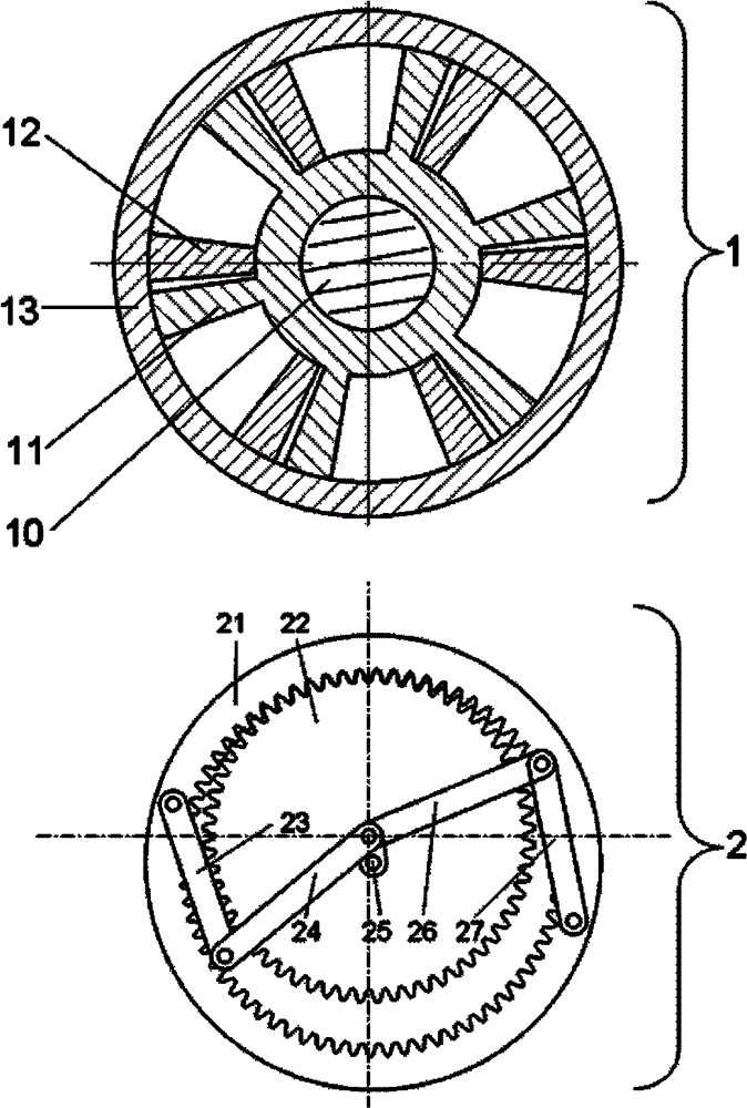
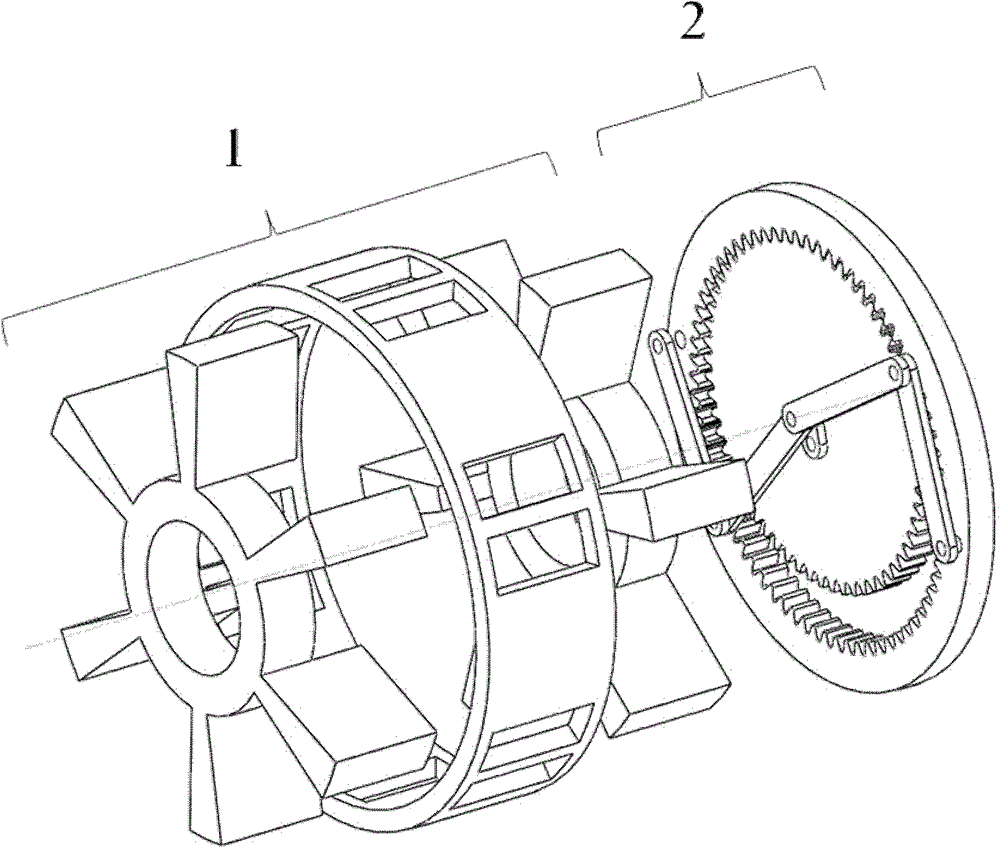
[0023] like figure 1 , figure 2 and image 3 As shown, the power transmission device combined with the cycloid mechanism and the double crank mechanism of the present invention includes a power cylinder assembly 1 and a differential drive assembly 2 connected with the power cylinder assembly 1. The power cylinder assembly 1 includes a rotor I11, a rotor II12, a power cylinder The shaft 10 , the cylinder 13 , the rotor I11 and the rotor II12 are coaxially and staggered (cross-shaped) installed in the cylinder 13 and rotate around the rotation axis of the power shaft 10 . That is, the power cylinder assembly 1 and the differential drive assembly 2 are coaxially arranged and assembled in combination through the respective cylinder blocks. In the power cylinder assembly 1, there are two rotors coaxially installed in the cylinder block 1...


PUM


Abstract

The invention discloses a power transmission device with a combined pericycloid mechanism and double-crank mechanisms, which comprises a power cylinder assembly and a differential driving assembly connected with the power cylinder assembly, wherein the power cylinder assembly comprises a rotor I, a rotor II, a power shaft and a cylinder body, and the rotor I and the rotor II are coaxially installed in the cylinder body in a staggered shape and rotate around a rotating axis of the power shaft; and the differential driving assembly is a combined mechanism formed by combining a set of pericycloid mechanism together with two sets of double-crank mechanisms, wherein the combined mechanism has the freedom of 1. The power transmission device has the advantages of simple and compact structure, stable, reliable and high-efficiency transmission, wide application range and the like, and when the power transmission device is used on an engine, a double-rotor piston engine with high efficiency andlarge power density can be obtained.

Description

technical field [0001] The invention mainly relates to the field of positive displacement machines, in particular to a power transmission device which can be applied to the fields of piston-type internal combustion engines, external combustion engines, pneumatic machines, compressors, pumps and the like. Background technique [0002] Positive displacement machines include mechanical equipment such as piston engines, compressors, and pumps. The present invention specifically relates to the improvement of the power transmission part of the engine, and the involved method and structure are also suitable for the improvement of equipment such as pneumatic machines, compressors, and pumps with a slight modification. [0003] There are two main types of piston engines: reciprocating piston engines and rotary piston engines. A crank-connecting rod mechanism is used for power transmission on most reciprocating piston engines. For more than 100 years, researchers have carried out ex...

Claims


Application Information

Patent Timeline
Patent Type & Authority Patents(China)
IPC IPC(8): F02B53/00F02B61/06
CPCY02T10/17Y02T10/12
Inventor 潘存云邓豪徐海军易声耀陈虎张文波
Owner NAT UNIV OF DEFENSE TECH
Why Eureka
Try Eureka