
Multi-degree-of-freedom-adjusting camera suspension bracket

A technology of camera and rotation adjustment, which is applied in the direction of machines/brackets, supporting machines, mechanical equipment, etc., which can solve the problems of inconvenience for manufacturers and users, secondary construction, and high cost of electric structures, and achieve good practicability and low price. cheap effect

Active Publication Date: 2021-06-25
SHENYANG FIRE RES INST OF MEM
View PDF13 Cites 0 Cited by
  • Summary
  • Abstract
  • Description
  • Claims
  • Application Information

AI Technical Summary

Problems solved by technology

[0004] 1. Cylindrical cameras with 1 degree of freedom or 2 degrees of freedom often face many problems such as installation difficulties and dead spots in monitoring, which lead to secondary construction, return and exchange of goods during use, and bring great harm to manufacturers and users. Inconvenience;
[0005] 2. Although the camera equipped with a large pan / tilt increases the degree of freedom to a certain extent, the electric structure adopted by the pan / tilt is not only expensive, but also easily damaged;
[0006] 3. The gimbal with 4 degrees of freedom for adjustment still cannot meet the existing use requirements

Method used


Image

  • Multi-degree-of-freedom-adjusting camera suspension bracket

Examples


Embodiment Construction

[0022] The specific implementation manners of the present invention will be further described in detail below in conjunction with the accompanying drawings and embodiments. The following examples are used to illustrate the present invention, but are not intended to limit the scope of the present invention.

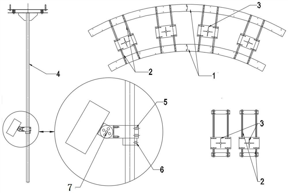
[0023] A multi-degree-of-freedom adjustable camera suspension bracket, such as figure 1 As shown, it includes arc-shaped installation base 1, double slideway slide rail 2, sliding adjustment plate 3, vertical cylinder 4, rotation adjustment fixing device 5, anti-falling safety locking device 6, camera fixing frame 7;

[0024] The arc-shaped installation base 1 is an arc-shaped stainless steel structure, which is fixedly installed on the ceiling of the building and has N fixing screw holes;

[0025] In this embodiment, the arc-shaped installation base 1 uses an arc-shaped stainless steel structure with a width of 40 cm, which is not only suitable for conventional complete ...


PUM


Abstract

The invention provides a multi-degree-of-freedom-adjusting camera suspension bracket, and relates to the technical field of camera installation and use. The multi-degree-of-freedom-adjusting camera suspension bracket comprises an arc-shaped mounting base, a double-slideway sliding rail, a sliding adjusting plate, a vertical cylinder, a rotary adjusting and fixing device, an anti-falling safety lock catch device and a camera fixing frame. The arc-shaped mounting base is fixedly mounted on a ceiling at the top of a building and is provided with N mounting and fixing screw hole positions; and the double-slideway sliding rail is installed on the arc-shaped mounting base, provided with screw installation holes and fixedly installed on the arc-shaped mounting base through screws, the sliding adjusting plate is provided with long-strip-shaped slideways and fastening screws, and the fastening screws pass through the long-strip-shaped slideways and then are fixed to the double-slideway sliding rail through nuts. The bracket adopts a stainless steel mechanical structure, and through the connection of a plurality of components, the six-degree-of-freedom adjustment of the camera is realized.

Description

technical field [0001] The invention relates to the technical field of camera installation and use, in particular to a multi-degree-of-freedom adjustable camera suspension bracket. Background technique [0002] The degree of freedom when the camera is installed determines the range that can be monitored, and a camera with multiple degrees of freedom has better flexibility and universality. Generally, the suspension mounting bracket of a cylindrical camera (usually called a bolt camera) can only adjust the viewing angle in 1 degree of freedom or 2 degrees of freedom, and even a camera equipped with a large pan / tilt can be adjusted in 4 degrees of freedom at most. [0003] After technical research and market feedback, the camera suspension mounting bracket has the following problems during use: [0004] 1. Cylindrical cameras with 1 degree of freedom or 2 degrees of freedom often face many problems such as installation difficulties and dead spots in monitoring, which lead to ...

Claims


Application Information

Patent Timeline
IPC IPC(8): F16M13/02F16M11/20F16M11/04F16M11/12F16M11/16
CPCF16M13/027F16M11/2085F16M11/2092F16M11/20F16M11/046F16M11/121F16M11/16
Inventor 田智嘉谢锋钟晨邵宇
Owner SHENYANG FIRE RES INST OF MEM
Learn More