Flow control valve for cylinders of liquefied gases, having a means for indicating the status of the fluid

Inactive Publication Date: 2005-04-14
CAVAGNA GROUP
View PDF7 Cites 7 Cited by
  • Summary
  • Abstract
  • Description
  • Claims
  • Application Information

AI Technical Summary

Benefits of technology

[0009] The aim of the present invention is to provide a device that is capable of giving an indication of the pressure of the fluid contained in the cyl

Problems solved by technology

However, the pressure gauge protrudes externally from the valve body and is exposed to accidental impacts that can

Method used


Image

  • Flow control valve for cylinders of liquefied gases, having a means for indicating the status of the fluid
  • Flow control valve for cylinders of liquefied gases, having a means for indicating the status of the fluid

Examples


Embodiment Construction

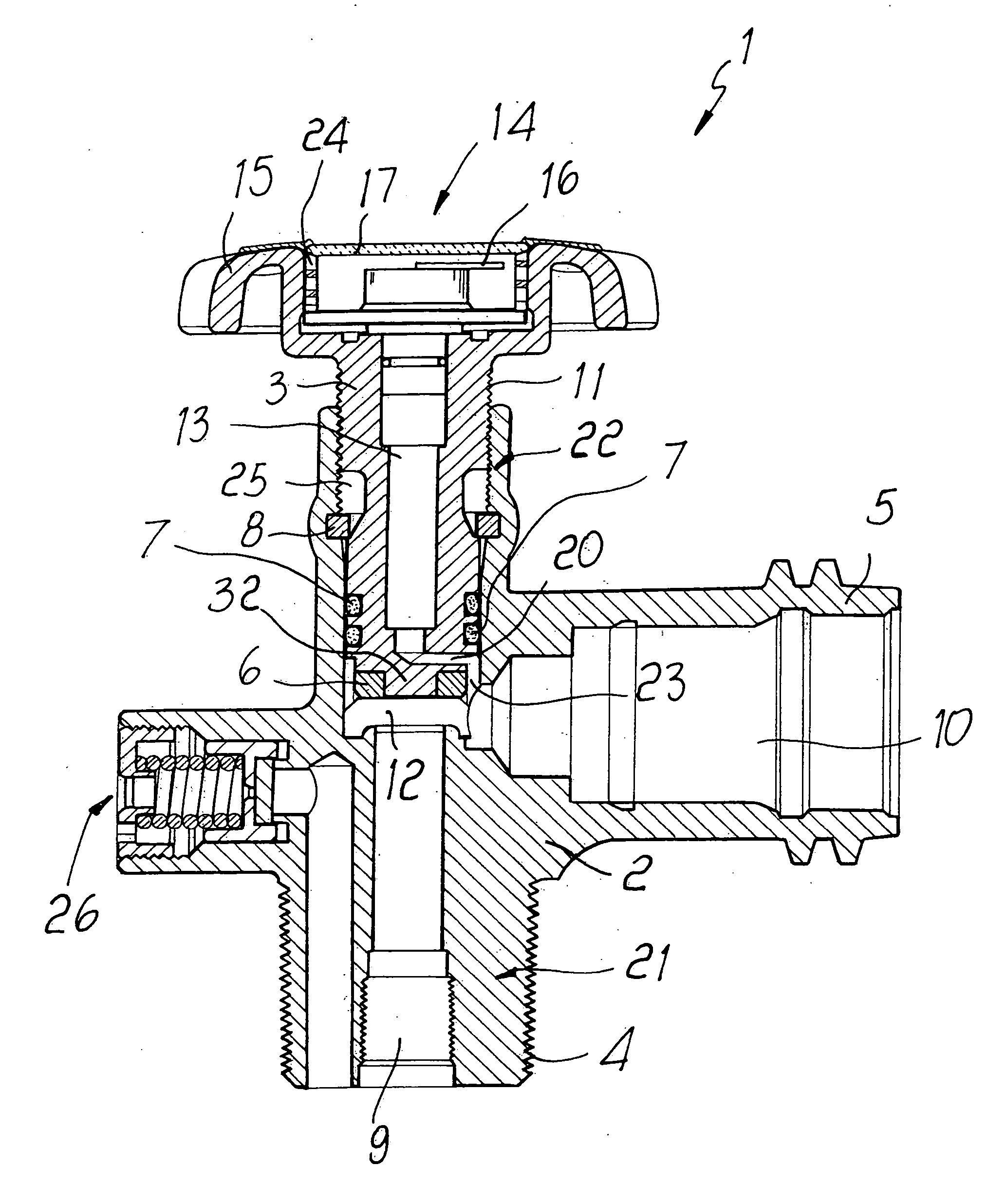
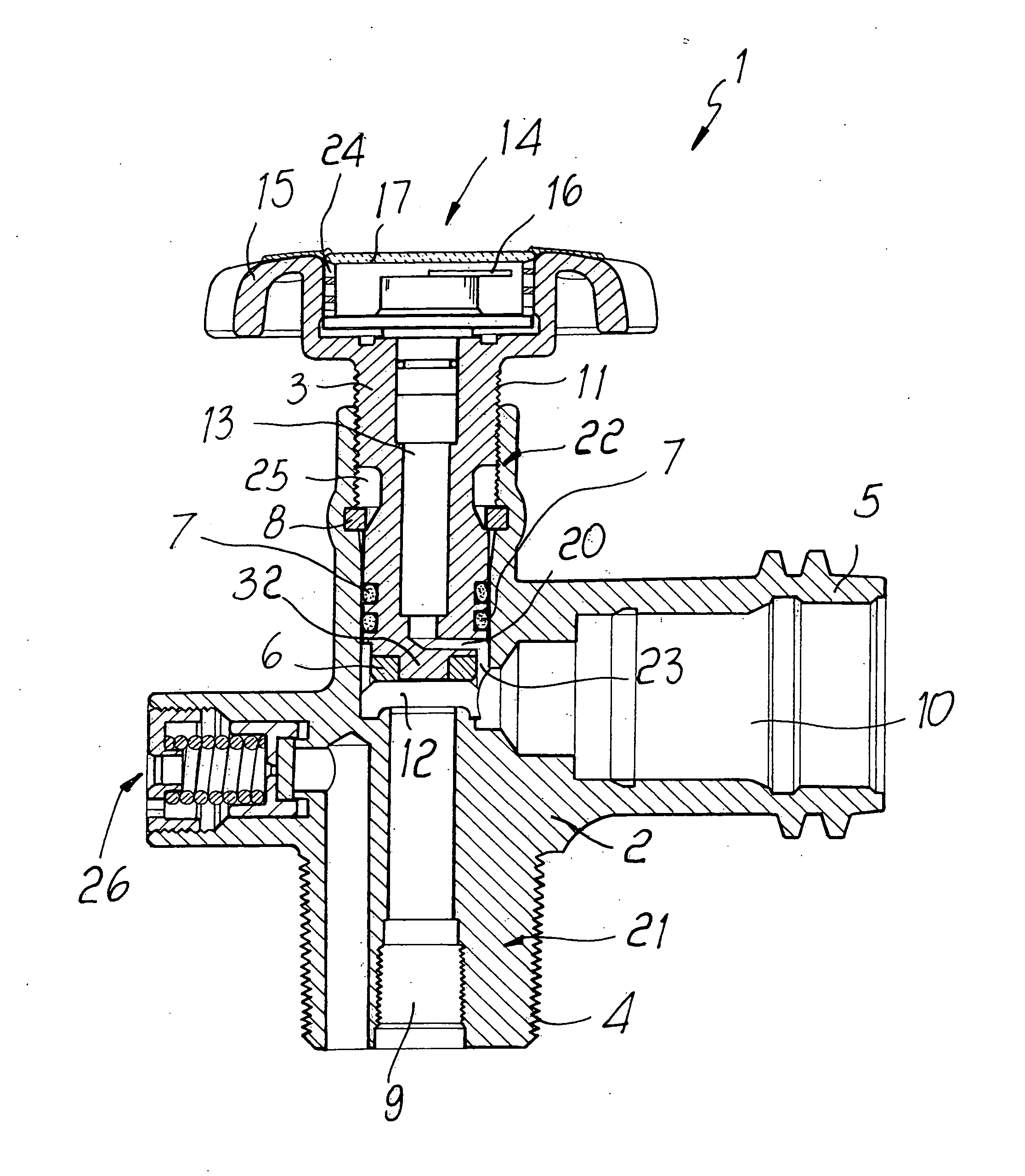
[0016] With reference to the cited FIGURE, a flow control valve for cylinders of liquefied gases, generally designated by the reference numeral 1, comprises a body 2 that is provided with an end 21, on which there is a threaded shank 4 adapted to be coupled hermetically to the cylinder on which the device is to be fitted, and with a region 5 that provides hermetic connection to the system for supplying the user devices.

[0017] A first supply duct 9 is provided inside the shank, and a second supply duct 10 is formed inside the region for connection to the user devices. The ducts allow the passage of the fluid that arrives from the cylinder and is directed to the user devices.

[0018] The ducts are mutually connected by a passage 12, which is provided in the region where they intersect.

[0019] The body 2 has a region 22, inside which a piston 3 is accommodated; the piston forms a movable closure member that is suitable to pass from an open position, in which the ducts 9 and 10 are mutu...


PUM


Abstract

A flow control valve for cylinders of liquefied gases having a gauge for indicating the status of the fluid, comprises a body in which there is a region provided with a shank that is adapted to be connected to a cylinder, a region for connection to user devices, a safety valve, and a movable actuation member, the actuation of which blocks the passage for the fluid from the cylinder toward the user device or clears the passage, a pressure gauge being accommodated inside the actuation member.

Description

BACKGROUND OF THE INVENTION [0001] 1. Field of the Invention [0002] The present invention relates to a flow control valve for cylinders or bottles of liquefied gases in general, industrial gases or the like, provided with a means for indicating the status of the fluid inside the cylinder. [0003] 2. Description of the Prior Art [0004] Ordinary cylinders containing liquefied gases or other gases are equipped with a conventional valve, by virtue of which they can be connected, either directly or by means of adapted pressure reduction units, to the user devices to be supplied. [0005] These conventional devices allow to separate, when required, the user devices from the cylinder in which the fluid is contained. [0006] In order to have an indication regarding the status of the fluid inside the cylinder, in conventional systems it is possible to connect, by means of a connector, a pressure gauge that is capable of indicating the pressure level of the fluid. [0007] However, the pressure gau...

Claims


Application Information

Patent Timeline
IPC IPC(8): F16K1/30F16K37/00G01L19/08
CPCF16K1/305G01L19/08F16K37/00F16K1/307Y10T137/8242Y10T137/8326
Inventor FREDERIKSEN, NIELS
Owner CAVAGNA GROUP
Why Eureka
Try Eureka