Filling element, filling system and method for filling containers
A technology for filling components and containers, applied in liquid filling, transportation and packaging, using back pressure perfusion, etc., can solve problems such as technical cost and power loss
- Summary
- Abstract
- Description
- Claims
- Application Information
AI Technical Summary
Problems solved by technology
Method used
Image


Examples
Embodiment Construction
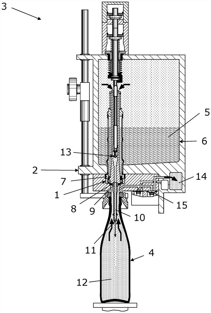
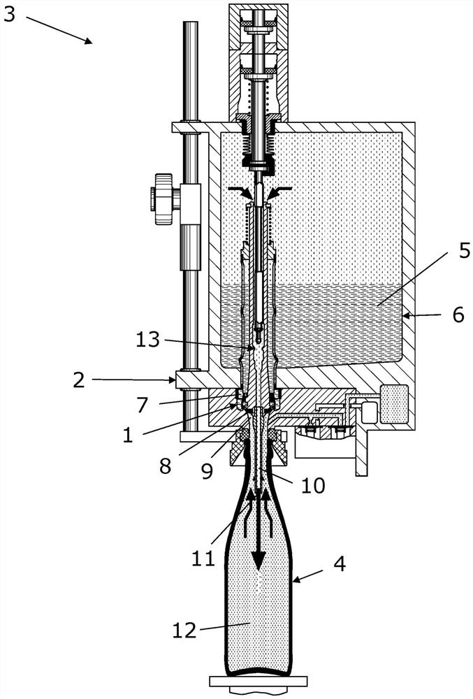
[0043] Figures 1a-1e A longitudinal section through a filling element 1 according to the invention is shown in each case by way of example at different points in time during the filling process. Here, the filling element 1 is arranged on a delivery element 2 of a filling system 3 , of which only a section is shown here.
[0044] Preferably during the filling process a container 4 is connected to the filling element 1 according to the invention, which container 4 is to be filled with a liquid filling 5 which is prepared in a filling reservoir 6 . exist Figures 1a-1e In the figure, the container 4 is shown as a bottle, however, the filling element 1 and the associated filling method are also suitable for other containers, such as jars or cups, with minor modifications customary in the industry.
[0045] In principle, every kind of liquid that can be filled in the container 4 can be considered as the liquid filler 5, however, in particular, the filling element 1 and the filling...
PUM
 Abstract
Description
Claims
Application Information
PatSnap Eureka turns technology decisions into work you can execute. Powered by our Innovation Knowledge Graph, it runs expert workflows across engineering, life sciences, materials and intellectual property. Get your review-ready output in minutes.


