Emergency department nursing bandaging supporting device

A support device and emergency treatment technology, which is applied in the field of medical equipment, can solve the problems of inconvenient movement of the patient's body position, and achieve the effect of convenient dressing and reducing the occupied space

Active Publication Date: 2021-07-02
AFFILIATED HOSPITAL OF YOUJIANG MEDICAL UNIV FOR NATTIES
View PDF18 Cites 4 Cited by
  • Summary
  • Abstract
  • Description
  • Claims
  • Application Information

AI Technical Summary

Problems solved by technology

When the ambulance picks up the patient, it is necessary to use a stretcher to transport the patient to the hospital bed. However, due to the heavy weight of adults, it often requires the cooperation of multiple doctors to transport the patient from the stretcher to the hospital bed.

Method used


Image

  • Emergency department nursing bandaging supporting device
  • Emergency department nursing bandaging supporting device
  • Emergency department nursing bandaging supporting device

Examples


Embodiment 1

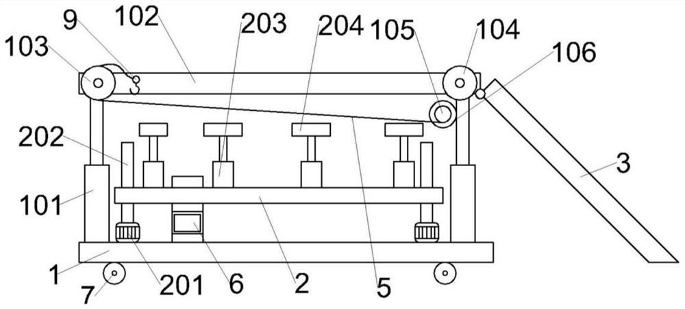
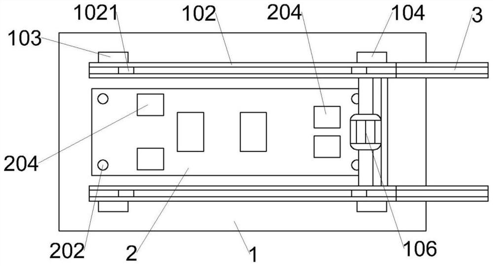
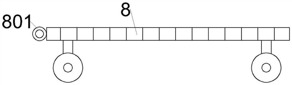
[0031] refer to Figure 1-4 As shown, the present embodiment provides a bandage support device for nursing care in the emergency department, including a support plate 1, the bottom of the support plate 1 is rotatably connected with a walking wheel 7, and the upper part of the support plate 1 is connected with two parallel groove slide rails 102 for lifting and lowering. , one end of the groove slide rail 102 is hinged with an inclined groove slide rail 3, a lifting support assembly is arranged between the two groove slide rails 102, the lifting support assembly is located between the support plate 1 and the groove slide rail 102, the support plate 1 A storage box 6 is fixedly connected to the top, and a pulling part is arranged outside the ends of the two grooved slide rails 102, and the pulling part is detachably connected to a stretcher 8 through the first wire rope 5.

[0032] In the present invention, a pulling part is arranged on the outer side of the groove slide rail 10...

Embodiment 2

[0045] refer to Figure 5-11 As shown, the difference between the supporting device of this embodiment and the first embodiment is only that,

[0046] The top surface of the support plate 1 is provided with a vertical chute, and a stop block 4 is slidingly connected in the vertical chute, and a spring 402 is fixedly connected between the bottom surface of the stop block 4 and the vertical chute, and the inclined groove slide rail 3 is far away from the vertical chute. One end of the grooved slide rail 102 is provided with an inclined surface, on which the first stop tooth 301 is fixedly connected, and the upper surface of the stop block 4 is fixedly connected with the second stop tooth 401, and the first stop tooth 301 is connected with the second stop tooth 401. Teeth 401 match each other, through the mutual cooperation of the first stop tooth 301 and the second stop tooth 401, when the inclined groove slide rail 3 is drooped by gravity, the stop can be realized to prevent th...


PUM


Abstract

The invention relates to the field of medical instruments, in particular to an emergency department nursing bandaging supporting device which comprises a supporting plate, wherein walking wheels are rotatably connected to the bottom of the supporting plate; two parallel groove sliding rails are connected to the upper portion of the supporting plate in a lifting mode; and inclined groove sliding rails are hinged to one ends of the groove sliding rails; a lifting supporting assembly is arranged between the two groove sliding rails and located between the supporting plate and the groove sliding rails; a storage box is fixedly connected to the top of the supporting plate; pulling parts are arranged on the outer sides of the ends of the two groove sliding rails; and the pulling parts are detachably connected with a stretcher through first steel wire ropes. According to the invention, medical personnel can conveniently carry out bandaging treatment on a patient.

Description

technical field [0001] The invention relates to the field of medical devices, in particular to a bandage support device for emergency care. Background technique [0002] In the emergency department of the hospital, patients with trauma to their arms or legs are often encountered. It is necessary to disinfect and bandage the patient's wound. When the ambulance receives the patient, it is necessary to use a stretcher to transport the patient to the hospital bed. However, due to the heavy weight of adults, it often requires the cooperation of multiple doctors to transport the patient from the stretcher to the hospital bed. After the patient is transported to the hospital bed, it is necessary to The patient is bandaged, because the patient's legs and arms are injured during bandaging, and there is a lot of inconvenience for the patient's body movement. There is no device in the existing medical equipment to assist the emergency department to treat the patient's arm or leg trauma...

Claims


Application Information

Patent Timeline
IPC IPC(8): A61G1/02A61G1/04A61G7/075
CPCA61G1/02A61G1/04A61G7/0755
Inventor 黄翠麦王建源陆启祥蒙瑜何彩霞
Owner AFFILIATED HOSPITAL OF YOUJIANG MEDICAL UNIV FOR NATTIES
Why Eureka
Try Eureka