Display device and electronic equipment

A technology of a display device and a touch electrode, which is applied to the input/output process of electrical digital data processing, instruments, and data processing, etc., can solve the problems of lowering the yield rate of the display device, and short-circuiting of multiple touch wires. Achieve the effect of reducing length difference, avoiding short circuit and improving product yield

Pending Publication Date: 2021-07-02
WUHAN CHINA STAR OPTOELECTRONICS SEMICON DISPLAY TECH CO LTD
View PDF3 Cites 2 Cited by
  • Summary
  • Abstract
  • Description
  • Claims
  • Application Information

AI Technical Summary

Problems solved by technology

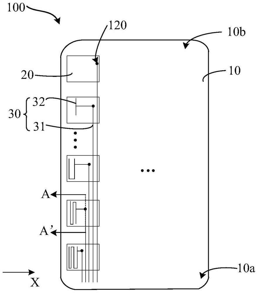
[0004] The present application provides a display device and electronic equipment to solve the problem that in the prior art, in order to reduce the impedance difference between multiple touch traces, short circuits easily occur between multiple touch traces arranged with equal lengths, which leads to Technical Issues of Display Device Yield Decrease

Method used


Image

  • Display device and electronic equipment
  • Display device and electronic equipment
  • Display device and electronic equipment

Examples


Embodiment Construction

[0036] The following will clearly and completely describe the technical solutions in the embodiments of the application with reference to the drawings in the embodiments of the application. Apparently, the described embodiments are only some of the embodiments of the application, not all of them. Based on the embodiments in this application, all other embodiments obtained by those skilled in the art without making creative efforts belong to the scope of protection of this application. In addition, it should be understood that the specific implementations described here are only used to illustrate and explain the present application, and are not intended to limit the present application. In this application, unless stated to the contrary, the used orientation words such as "up" and "down" usually refer to up and down in the actual use or working state of the device, specifically the direction of the drawing in the drawings ; while "inside" and "outside" refer to the outline of ...


PUM


Abstract

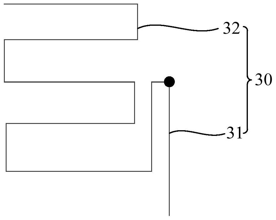
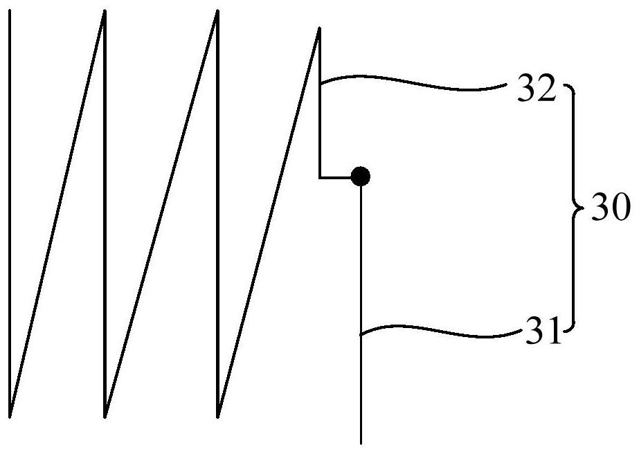
The invention discloses a display device and electronic equipment. The display device comprises a substrate, a plurality of touch electrodes and a plurality of touch wires. The substrate is provided with a first end and a second end which are oppositely arranged. The number of the touch electrodes is multiple, and the multiple touch electrodes are arranged on the substrate in an array mode. The touch wires are arranged on the substrate, the touch electrodes and the touch wires are located on different layers, and the touch electrodes and the corresponding touch wires are connected through via holes. Part of the plurality of touch wires comprises a first branch line and a second branch line which are connected with each other, the first branch line extends to the corresponding touch electrode from the first end to the second end so as to be connected with the corresponding touch electrode, the second branch line is located in an area corresponding to the touch electrode connected with the second branch line, and the second branch line is used for adjusting the length of the touch control wire. According to the invention, short circuit among the plurality of touch wires corresponding to the plurality of touch electrodes in the same column can be avoided, so that the product yield is improved.

Description

technical field [0001] The present application relates to the field of display technology, in particular to a display device and electronic equipment. Background technique [0002] With the development of touch technology, electronic devices with touch function are widely used in people's life and work, and display panels with touch function have become a research hotspot in the field of display. The touch structure of the existing touch display panel includes an add-on touch structure, a touch on cell structure and a touch incell structure. [0003] Wherein, the on-panel touch structure and the in-plane touch structure can greatly reduce the overall thickness of the touch display panel. Existing on-panel touch structures and in-plane touch structures can be classified into self-capacitance and mutual-capacitance. In order to reduce the impedance difference between multiple touch traces, the touch traces in the self-capacitive touch control often adopt an equal-length desi...

Claims


Application Information

Patent Timeline
Patent Type & Authority Applications(China)
IPC IPC(8): G06F3/041G06F3/044
CPCG06F3/0443G06F3/04164G06F3/0442
Inventor 梁超刘旭阳
Owner WUHAN CHINA STAR OPTOELECTRONICS SEMICON DISPLAY TECH CO LTD
Why Eureka
Try Eureka