
Wiped film type flash evaporator

A technology of scraping film and flash evaporation, which is applied in the direction of flash evaporation, evaporation, evaporator accessories, etc., and can solve the problems of low production efficiency

Inactive Publication Date: 2021-07-06
SHANGHAI PILOTECH INSTR & EQUIP
View PDF6 Cites 0 Cited by
  • Summary
  • Abstract
  • Description
  • Claims
  • Application Information

AI Technical Summary

Problems solved by technology

[0004] In view of the related technologies mentioned above, the staff injects liquid materials into the evaporation tube so that the volume of the liquid in the evaporation tube does not exceed 50% of the volume of the evaporation tube. Heating the materials. When there are many liquid materials to be concentrated, it is necessary to heat the liquid materials in batches. The inventor believes that there is a defect of low production efficiency.

Method used


Image

  • Wiped film type flash evaporator
  • Wiped film type flash evaporator
  • Wiped film type flash evaporator

Examples


Embodiment Construction

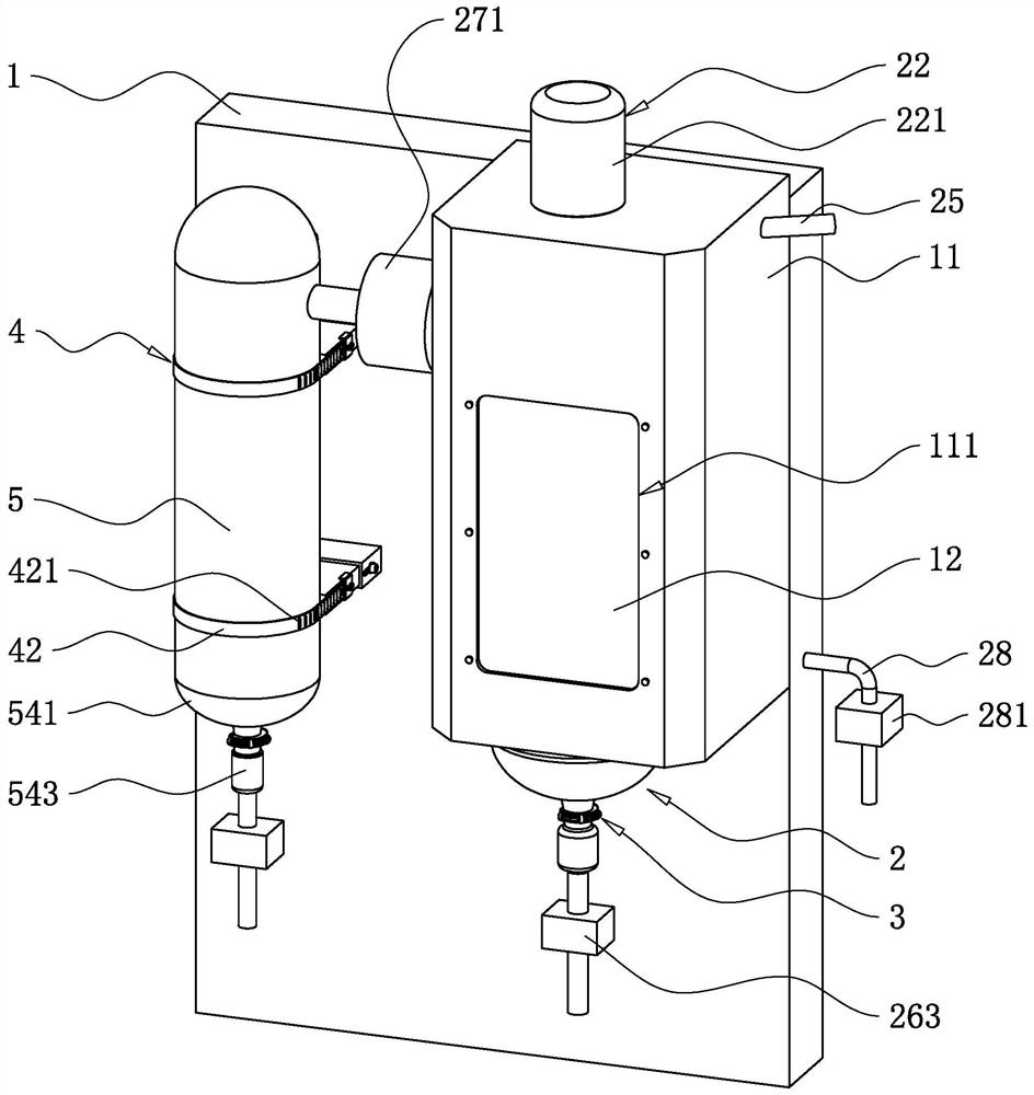
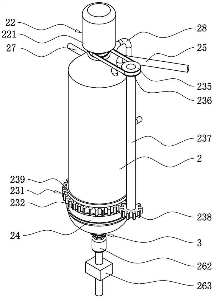
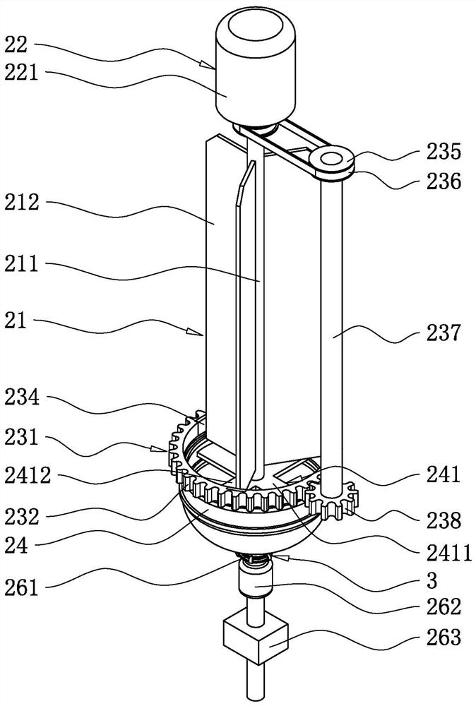
[0039] The following is attached Figure 1-7 The application is described in further detail.

[0040] The embodiment of the present application discloses a wiped film flash evaporator.

[0041] see figure 1 , figure 2 , the wiped film flash evaporator includes a frame 1, the frame 1 is vertically arranged, and one side of the width direction of the frame 1 is provided with a mounting frame 11, and the mounting frame 11 is located on one side of the frame 1 lengthwise direction. An evaporation tube 2 is arranged in the installation frame 11 , and the evaporation tube 2 is vertically arranged, and a film scraping device 21 is arranged in the evaporation tube 2 . A heating device 23 is also arranged in the installation frame 11 . The frame 1 is provided with a condensation pipe 5 along its own length direction away from the side of the mounting frame 11. The condensation pipe 5 is vertically arranged, and the upper side of the evaporation pipe 2 is connected with an air outl...


PUM


Abstract

The invention relates to a wiped film type flash evaporator. The flash evaporator comprises a rack, an evaporation pipe is vertically arranged in the rack, the upper side of the evaporation pipe is communicated with a feeding pipe, and the lower side of the evaporation pipe is communicated with a discharging pipe. A heating device used for heating the outer side wall of the evaporation pipe is further arranged in the rack. A rotating shaft is arranged in the evaporation pipe, the rotating shaft is vertically arranged, and the rotating shaft and the evaporation pipe are coaxially arranged. A wiped film plate is arranged on one side of the rotating shaft in the radial direction, the wiped film plate is vertically arranged, the side, away from the rotating shaft, of the wiped film plate in the width direction of the wiped film plate is fixedly connected with the rotating shaft, and the side, away from the rotating shaft, of the wiped film plate in the width direction of the wiped film plate and the inner side wall of the evaporation pipe are arranged at an interval. A driving assembly used for driving the rotating shaft to rotate around the axis of the rotating shaft is arranged at the upper end of the rotating shaft, a vacuum pump is arranged on the upper side of the evaporation pipe in a communicated mode, and the inlet of the vacuum pump is communicated with the evaporation pipe. The flash evaporator has the effect of improving the production efficiency.

Description

technical field [0001] The present application relates to the technical field of liquid concentration equipment, in particular to a wiped-film flash evaporator. Background technique [0002] In the process of chemical production or pharmaceutical production, it is often necessary to concentrate liquid materials to obtain finished products with higher concentrations. [0003] In a laboratory or factory, an evaporator includes a frame, a fluid heating pot on the frame, an evaporation tube is arranged in the fluid heating pot, and a condensation pipe is arranged on the frame. The condensation pipe is vertically arranged, and the condensation pipe is connected to the The tube opening of the evaporating tube is communicated, and the evaporating tube is arranged obliquely downward from the side close to the condensing tube to the side away from the condensing tube. The outlet at the lower end of the condensation pipe is communicated with a collecting bottle. The liquid material ...

Claims


Application Information

Patent Timeline
IPC IPC(8): B01D1/22B01D1/30B01D3/06
CPCB01D1/22B01D1/30B01D3/06
Inventor 胡友华
Owner SHANGHAI PILOTECH INSTR & EQUIP
Learn More