
Reversible micro-fluidic chip clamp

A technology of microfluidic chips and fixtures, which is applied to manufacturing tools, workpiece clamping devices, etc., can solve the problems of inconvenient rotation and connection of microfluidic chips.

Inactive Publication Date: 2021-07-06
陈雪
View PDF0 Cites 0 Cited by
  • Summary
  • Abstract
  • Description
  • Claims
  • Application Information

AI Technical Summary

Problems solved by technology

[0005] The purpose of the present invention is to provide a reversible microfluidic chip fixture to solve the problem that the microfluidic chip is inconvenient to rotate at different angles to connect with the fluid conduit

Method used


Image

  • Reversible micro-fluidic chip clamp
  • Reversible micro-fluidic chip clamp
  • Reversible micro-fluidic chip clamp

Examples


Embodiment Construction

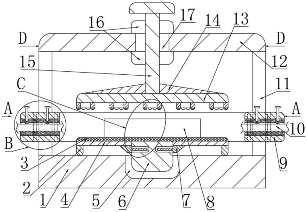
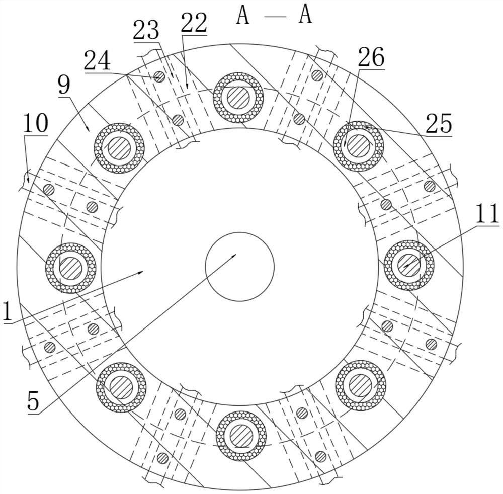
[0029] see figure 1 , figure 2 and Figure 6 , a reversible microfluidic chip fixture, including a bottom plate 1, the bottom plate 1 is a circular structure; the top of the bottom plate 1 is provided with a groove 5, and the groove 5 is a circular structure; the inside of the groove 5 is inserted with a rotary table 6, and the rotary table The height of 6 is not less than the depth of groove 5.

[0030] see figure 1 , figure 2 and Figure 6 , the rotary table 6 is rotatably connected to the bottom plate 1 through the groove 5, and is used to drive the microfluidic chip 8 to rotate, and adjust the angle of the connection between the microfluidic chip 8 and the fluid conduit 10; the side of the rotary table 6 is equipped with a support bar 4 , the support bar 4 is an elongated structure, the top of the support bar 4 is flush with the top of the turntable 6, the support bar 4 is parallel to the base plate 1, and the length of the support bar 4 is not greater than the radi...


PUM


Abstract

The invention discloses a reversible micro-fluidic chip clamp. The clamp comprises a bottom plate, a groove is formed in the top end of the bottom plate, a rotating table is inserted into the interior of the groove, supporting strips are installed on the side face of the rotating table, supporting columns are fixed to one ends of the supporting strips, reinforcing blocks are fixed to the other ends of the supporting strips, inserting rods are fixed to the side faces of the reinforcing blocks, inserting holes are formed in the side face of the rotating table, the inserting rods are inserted into the inserting holes, a non-slip mat is adhered to the top ends of the supporting strips, and a micro-fluidic chip is placed at the top end of the non-slip mat. The micro-fluidic chip can be driven to rotate through an adjusting rod and the rotating table, and the connecting angle of the micro-fluidic chip and a fluid conduit is adjusted. According to the size of the micro-fluidic chip, the supporting strips with different lengths are inserted to support the micro-fluidic chip. The height of a mounting plate is adjusted, so that the fluid conduit is located at a reasonable position, and the fluid conduit is connected with the micro-fluidic chip.

Description

technical field [0001] The invention belongs to the technical field of microfluidic chips, in particular to a clamp for a reversible microfluidic chip. Background technique [0002] Microfluidic chip technology integrates the basic operation units such as sample preparation, reaction, separation, and detection in the process of biological, chemical, and medical analysis into a micron-scale chip to automatically complete the entire analysis process. Microfluidic chips have the advantages of small size, less use of reagents, and high integration. More and more researchers have begun to pay attention to microfluidic chips; due to its great potential in the fields of biology, chemistry, and medicine, it has become a A brand-new research field that intersects disciplines such as biology, chemistry, medicine, and fluids. [0003] The reversible microfluidic chip fixture is a fixture that detachably installs and connects the microfluidic chip and the fluid conduit, which is conven...

Claims


Application Information

Patent Timeline
IPC IPC(8): B25B11/02
CPCB25B11/02
Inventor 陈雪
Owner 陈雪
Learn More