
Rotary wheel mark scrubbing equipment on vacuum tube production equipment

A production equipment and rotary printing technology, applied in the field of vacuum tubes, can solve the problems of broken thorns stuck in the scratches of vacuum tubes, broken thorns of glass on the printing belt, etc.

Inactive Publication Date: 2021-07-06
广州斑超电子科技有限公司
View PDF4 Cites 0 Cited by
  • Summary
  • Abstract
  • Description
  • Claims
  • Application Information

AI Technical Summary

Problems solved by technology

[0003] Based on the above description, the inventors have found that the scrubbing wheel printing equipment on the existing vacuum tube production equipment mainly has the following deficiencies, such as: in the process of scrubbing the vacuum tube with the wiper, the wiper wraps the outer wall of the vacuum tube, and the polished The formed glass broken thorns are pressed on the vacuum tube to scrub back and forth, and the glass broken thorns rub against the vacuum tube to form scratches of different depths, causing the broken thorns to be stuck in the scratches of the vacuum tube, causing the runner to print the number on the vacuum tube When the printing tape is damaged by the friction of glass thorns in the scratch

Method used


Image

  • Rotary wheel mark scrubbing equipment on vacuum tube production equipment
  • Rotary wheel mark scrubbing equipment on vacuum tube production equipment
  • Rotary wheel mark scrubbing equipment on vacuum tube production equipment

Examples


Embodiment 1

[0030] as attached figure 1 To attach Figure 6 Shown:

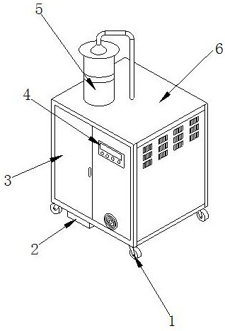
[0031] The invention provides a vacuum tube production equipment scrubbing wheel printing equipment, the structure of which includes a bottom wheel 1, an electric box 2, a placement door 3, a control panel 4, a water storage tank 5, and a working box 6. The upper end of the bottom wheel 1 is threaded Connected to the lower end of the working box 6, the upper end of the electric box 2 is connected to the lower end of the working box 6 by studs, the rear end of the placement door 3 is bolted to the front end of the working box 6, and the rear end of the control panel 4 is embedded and connected to the placement door 3 front end, the lower end of the water storage tank 5 is fixedly connected to the upper end of the working box 6.

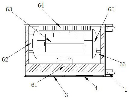
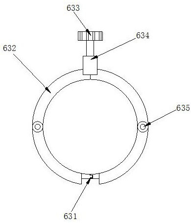
[0032] Wherein, the working box 6 is provided with a printing box 61, a rotating column 62, a scrubbing device 63, a slide rail 64, a vibrating device 65, and a chip removal groove 66, and the ...

Embodiment 2

[0040] as attached Figure 7 To attach Figure 9 Shown:

[0041] The present invention provides a device for scrubbing the wheel marks on vacuum tube production equipment. The vibrating device 65 is provided with a vibrating plate 651, a bumper 652, a connecting plate 653, a guide port 654, and a push bar 655. The inner side of the vibrating plate 651 is embedded The connecting plate 653 is set between the vibrating plates 651 for supporting fit, the inner side of the guide port 654 fits with the outer side of the push bar 655, and the outer side of the push bar 655 is engaged with The inner side of the push block 652 is slidably fitted, and the outer side of the push bar 655 is provided with two pulleys, which are respectively stuck on the inner side of the collision block 652, so that when the vacuum tube is rotating, it will be slowly rotated and wiped with the sliding of the push bar 655 to prevent the vacuum tube from appearing on the outside. wear and tear.

[0042] W...


PUM


Abstract

The invention discloses rotary wheel mark scrubbing equipment on vacuum tube production equipment. The rotary wheel mark scrubbing equipment structurally comprises bottom wheels, an electric box, a placement door, a control panel, a water storage tank and a working box, wherein the upper ends of the bottom wheels are in threaded connection with the lower end of the working box, the upper end of the electric box is in stud connection with the lower end of the working box, the rear end of the placement door is in bolt connection with the front end of the working box, the rear end of the control panel is fixedly connected to the front end of the placement door in an embedded mode, and the lower end of the water storage tank is fixedly connected to the upper end of the working box. The equipment is powered on, the placement door is opened, a vacuum tube is placed in a vibration device and a scrubbing device, the control panel is controlled, a driving wheel in a rotating wheel drives a scrubbing plate to expand and be recycled, buckles are clamped to support the vibration tube, and the control panel is controlled, so that a rotating column drives the vacuum tube in the vibration device to rotate, pulleys in the scrubbing device continuously slide left and right in a sliding rail, the vacuum tube is scrubbed, and it is avoided that the outer edge face of the vacuum tube is pressed and covered, causing abrasion of broken thorns, scratches left on the outer surface, and damage to a printing belt.

Description

technical field [0001] The invention belongs to the field of vacuum tubes, and in particular relates to a scrubbing wheel printing device on vacuum tube production equipment. Background technique [0002] During the production process of the vacuum tube, it is cut and polished according to the required length and the thickness of the tube wall. After the wiper is used to squeeze and scrub the vacuum tube around the vacuum tube, after the production is completed, the batch is printed on the vacuum tube by the printing tape on the runner. number to classify. [0003] Based on the above description, the inventors found that the scrubbing wheel printing equipment on the existing vacuum tube production equipment mainly has the following deficiencies, such as: in the process of scrubbing the vacuum tube with the wiper, the wiper wraps the outer wall of the vacuum tube, and the polished The formed glass broken thorns are pressed on the vacuum tube to scrub back and forth, and the ...

Claims


Application Information

Patent Timeline
Patent Type & Authority Applications(China)
IPC IPC(8): B41F35/00B41F23/00
CPCB41F35/00B41F35/007B41F23/005B41P2235/20B41P2235/50
Inventor 陈诗意
Owner 广州斑超电子科技有限公司
Learn More