Airplane control surface gap measuring device

A technology of measuring device and rudder surface, which can be used in aircraft component testing and other directions, which can solve the problems of inconvenient operation and high testing cost.

Inactive Publication Date: 2021-07-06
CHENGDU AIRCRAFT INDUSTRY GROUP
View PDF9 Cites 2 Cited by
  • Summary
  • Abstract
  • Description
  • Claims
  • Application Information

AI Technical Summary

Problems solved by technology

This leads to a large number of detection equipment, high detection cost, and very inconvenient operation

Method used


Image

  • Airplane control surface gap measuring device
  • Airplane control surface gap measuring device
  • Airplane control surface gap measuring device

Examples


Embodiment 1

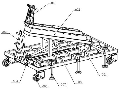
[0032] A kind of aircraft rudder surface gap measuring device of the present embodiment, such as figure 1 , Figure 4 , Figure 9 As shown, it includes a main body bracket and a turning part 002 arranged on the main body bracket. The connecting end of the turning part 002 is pivotally hinged with the top of the main body bracket. The driving end of the connecting rod 003 is slidingly connected to the top of the main body bracket, and the supporting end of the connecting rod 003 is hinged to the bottom of the turning part 002; The driving mechanism 001; on the side of the overturning part 002 away from the main body support, a sliding lift frame 026 is slid along the length direction of the overturning part 002, and a driving sliding frame 026 is provided between the sliding lifting frame 026 and the overturning part 002. The lifting frame 026 is a linear sliding module 024 that slides, and the force applying device 005 is detachably arranged on the sliding lifting frame or t...

Embodiment 2

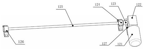
[0038] This embodiment is further optimized on the basis of embodiment 1, such as Figure 7 and Figure 8 As shown, the force applying device 005 includes a force applying device skeleton 051, a force applying linear movement mechanism, a ball joint 055, and a force sensor 056, and the force applying device skeleton 051 is arranged on the sliding lifting frame 026 or on the main body support , the end of the force applying device skeleton 051 away from the sliding lifting frame is provided with a force applying linear movement mechanism, the moving end of the force applying linear movement mechanism is connected to one end of the force sensor 056, and the other end of the force sensor 056 A ball joint 055 is provided.

[0039] The connecting end of the force applying device skeleton 051 is directly installed on one end of the sliding lifting frame 026 or on the top of the main body bracket through connecting bolts. It is directly connected with the ball and socket universal ...

Embodiment 3

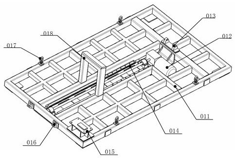
[0045] This embodiment is further optimized on the basis of above-mentioned embodiment 1 or 2, such as figure 2 As shown, the overturn driving mechanism 001 includes a linear guide rail 014, an overturn component mounting support 013 fixedly installed at one end of the linear guide rail 014, a sliding support 004 slidably arranged on the linear guide rail 014, and an overturning device that drives the sliding support 004 to slide. The linear drive mechanism 012, the connecting end of the turning part 002 is hinged on the top of the turning part mounting support 013, and the driving end of the connecting rod 003 is hinged on the top of the sliding support 004.

[0046] Such as figure 2 and Figure 6 As shown, the main body bracket includes a main body frame 011, the top of the main body frame 011 is provided with a mounting groove along the midline in the length direction, two linear guide rails 014 are arranged in parallel alignment in the mounting groove, and the bottom si...


PUM


Abstract

The invention discloses an airplane control surface gap measuring device, which comprises a main body support and an overturning part arranged on the main body support, the connecting end of the overturning part is rotatably hinged with the top of the main body support, a connecting rod is arranged between the overturning part and the main body support, and the driving end of the connecting rod is slidably connected with the top of the main body support. The supporting end of the connecting rod is hinged to the bottom of the overturning part. An overturning driving mechanism for driving the driving end of the connecting rod to linearly slide is also arranged on the main body support; a sliding lifting frame is slidably arranged on the side, away from the main body support, of the overturning part in the length direction of the overturning part, a linear sliding module for driving the sliding lifting frame to slide is arranged between the sliding lifting frame and the overturning part, and a force application device is detachably arranged on the sliding lifting frame or the main body support. According to the invention, the height and angle of the force application device can be flexibly adjusted, so that control surfaces with different heights and angles can be detected in a compatible manner.

Description

technical field [0001] The invention belongs to the technical field of aircraft rudder surface clearance measuring devices, and in particular relates to an aircraft rudder surface clearance measuring device. Background technique [0002] Aircraft rudder surfaces mainly include vertical tail rudder, canards, ailerons and flaps, etc., which are mainly used to control the pitch and lateral control of the aircraft; in aircraft control, the ailerons and rudder cooperate to realize the turning of the aircraft, and the ailerons complete Roll, rudder completes yaw. [0003] The connection between the aircraft rudder surface and the aircraft is mainly hinged, and the rotation angle of the rudder surface is controlled by the actuator. There will be errors in the process of aircraft parts manufacturing and component assembly. After accumulation, there will be a rotation gap on the rudder surface. When the rotation gap is out of tolerance, the flight control system cannot compensate th...

Claims


Application Information

Patent Timeline
Patent Type & Authority Applications(China)
IPC IPC(8): B64F5/60
CPCB64F5/60
Inventor 陈亮孟华林王振文孙永亮
Owner CHENGDU AIRCRAFT INDUSTRY GROUP
Why Eureka
Try Eureka