Eureka AIR delivers breakthrough ideas for toughest innovation challenges, trusted by R&D personnel around the world.

Push-button switch

A switch and button technology, which is applied in the field of retaining structure of terminals, can solve the problems of deterioration of installation performance, inclination of terminal circuit boards, and penetration of flux into housing 11, etc., and achieves the effect of simple structure and prevention of twisting and bending.

Inactive Publication Date: 2003-12-10
ALPS ALPINE CO LTD
View PDF0 Cites 0 Cited by
  • Summary
  • Abstract
  • Description
  • Claims
  • Application Information

AI Technical Summary

Problems solved by technology

[0006] However, in the above-mentioned conventional push button switch structure, since the fixed contact made of a round wire is arranged on the inner bottom surface of the synthetic resin housing 11 and the other end protrudes outward to the outer surface of the housing 11, The connecting terminal 12 is formed and formed along the outer surface of the housing 11 The connecting terminal 12 is formed in a curved and drooping shape, so the connecting terminal 12 is easily twisted on the protruding part protruding from the housing 11 because it is a round wire. Will tilt, so there is a problem that the installation performance deteriorates
[0007] In addition, since the connecting terminal 12 is formed to hang down along the outer surface of the housing 11, when the switch is mounted on the circuit board by soldering, there is a small gap between the soldering flux along the outer surface of the housing 11 and the connecting terminal 12. gaps and intrusion into the interior of the housing 11 by capillarity

Method used


Image

  • Push-button switch
  • Push-button switch
  • Push-button switch

Examples


Embodiment Construction

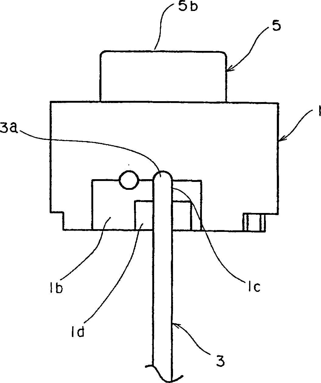
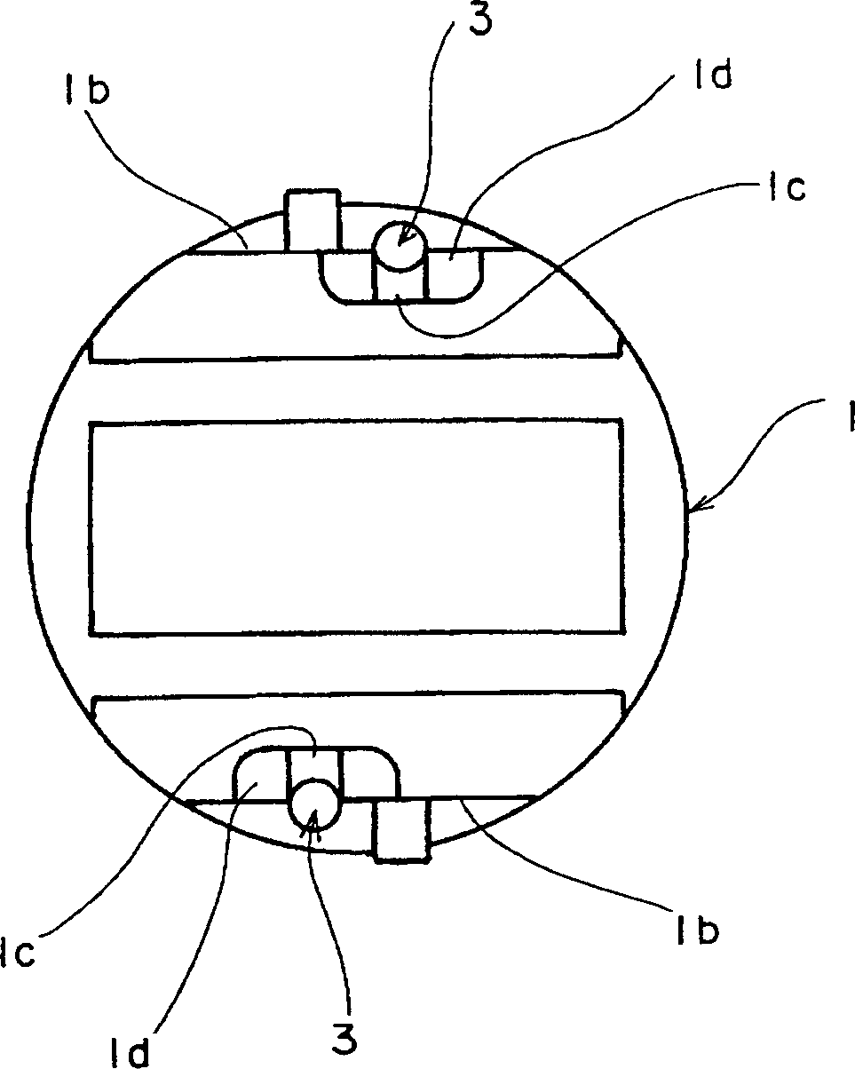
[0025] exist Figure 1 to Figure 6 Among them, the casing 1 is made of an insulating material such as synthetic resin and it has a bottomed box shape with an accommodating portion 1a therein. On the inner bottom surface of the accommodating portion 1a of the case 1, opposing fixed contacts 2, 2 composed of a pair of circular wires are arranged. The other ends of the fixed contacts 2, 2 protrude beyond the outer surface of the housing 1, so that the protruding free ends respectively form wirings connected to the circuit patterns of the electric circuit board, etc. not shown. Terminal 3. In addition, the connection terminal 3 is formed pendulously along the outer surface of the housing 1 and is bent into a Shaped curved portion 3a.

[0026] A pair of flat portions 1b on which the connection terminals 3 protrude are formed on the outer side of the housing 1 . On the flat portion 1b, a longitudinal groove 1c extending perpendicular to the bottom surface of the housing 1 from ...


PUM


Abstract

The invention provides a structure of a push button switch, which equipped with the housing formed in box shape with bottom having a containing part, the fixed contact projecting on the inner surface of the bottom of the housing, the connecting terminal projecting to the outside of the housing derived from the contact, and a movable contact contained in the part capable of connection and disconnection with the contact. The terminal is bent on the outside of the housing and vertically suspended along the face. A terminal holding part to prevent the bend of the terminal is formed by engaging the terminal.

Description

technical field [0001] The present invention relates to a push-button switch used as a switch for operation of electrical appliances and communication instruments, and more particularly to a holding structure for a connecting terminal drawn out from a casing. Background technique [0002] Figure 7 and Figure 8 The structure of a conventional push button switch is shown. Figure 7 is the front view of the push button switch, Figure 8 is its bottom view. [0003] In the drawing, a casing 11 is formed of an insulating material such as synthetic resin and formed in the shape of a bottomed box in which an accommodating portion (not shown) is contained. On the inner bottom surface of the accommodating portion of the housing 11, fixed contacts (not shown) composed of a pair of metal wires (round wires), the other ends of which protrude to the bottom of the housing 11, are provided. Outside of the outer side and thus formed are connection terminals 12 connected to a circuit pa...

Claims


Application Information

Patent Timeline
Patent Type & Authority Patents(China)
IPC IPC(8): H01H13/04H01H13/52
CPCH01H13/04H01H13/52
Inventor 冈田充弘佐藤秀隆吉田喜郎
Owner ALPS ALPINE CO LTD
Why Eureka
Eureka Blog
Learn More