
Alternating current and direct current withstand voltage partial discharge test device

A test device and pressure-resistant bureau technology, which is applied in the direction of measuring device, measuring device braking, measuring device shell, etc., can solve the problems of staff exiting the dangerous area, inability to conveniently transfer, lack of staff protection, etc.

Pending Publication Date: 2021-07-06
江苏恒润电力设计院有限公司
View PDF0 Cites 0 Cited by
  • Summary
  • Abstract
  • Description
  • Claims
  • Application Information

AI Technical Summary

Problems solved by technology

[0004] The purpose of the present invention is to solve the problem that the test device in the prior art lacks protection for the staff during use, cannot effectively make the staff exit the dangerous range during use, and often cannot be transferred conveniently, and is inconvenient to use. shortcoming, and proposed a kind of AC and DC withstand voltage partial discharge test device

Method used


Image

  • Alternating current and direct current withstand voltage partial discharge test device
  • Alternating current and direct current withstand voltage partial discharge test device
  • Alternating current and direct current withstand voltage partial discharge test device

Examples


Embodiment 1

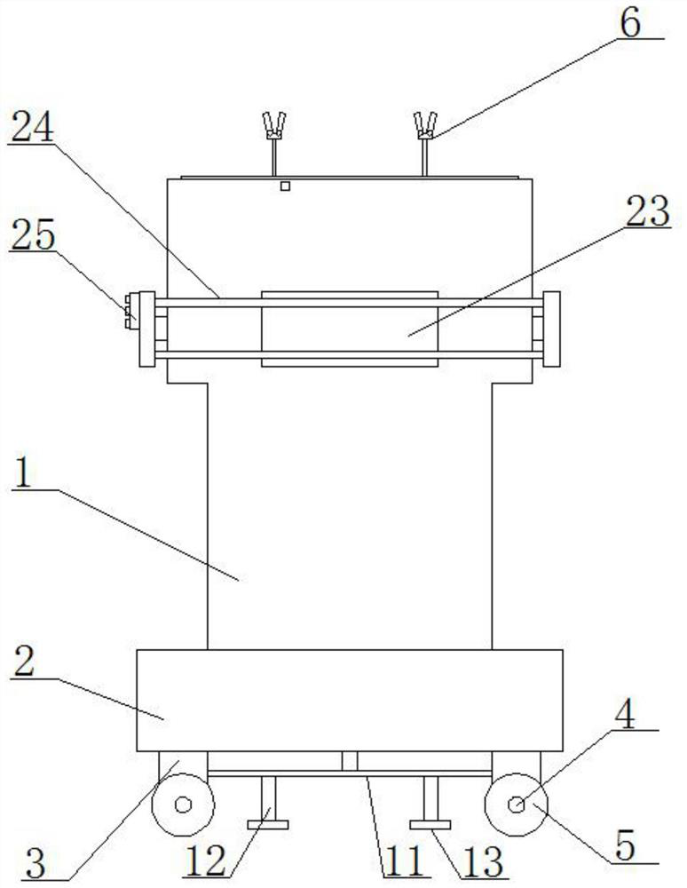
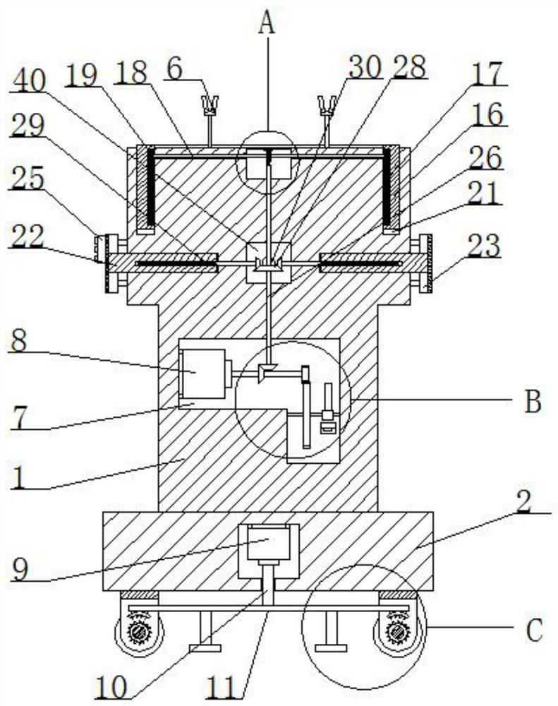
[0029] refer to Figure 1-5 , a kind of AC and DC partial discharge test device, comprising a test device body 1, the bottom of the test device body 1 is fixedly connected with a mobile base 2, and the bottom of the mobile base 2 is fixedly connected with two U-shaped plates 3, two U-shaped Axles 4 are installed on the plate 3 to rotate, and wheels 5 are fixedly connected to both ends of the two axles 4. A limit mechanism is arranged on the mobile base 2, and the limit mechanism cooperates with the two axles 4. The top of the test device body 1 There are two circuit clamps 6, a motor cavity 7 is opened in the test device body 1, and a forward and reverse motor 8 is fixedly installed in the motor cavity 7, a protective mechanism is installed on the top of the test device body 1, and a There is an isolation belt mechanism, and the reversing motor 8 cooperates with the protective mechanism and the isolation belt mechanism.

[0030] In this embodiment, the limit mechanism include...

Embodiment 2

[0040] refer to Figure 1-5 , an AC / DC voltage withstand partial discharge test device, comprising a test device body 1, the bottom of the test device body 1 is fixedly connected with a mobile base 2 by welding, and the bottom of the mobile base 2 is fixedly connected with two U-shaped plates 3 by welding, Both U-shaped plates 3 are rotatably equipped with axles 4, and the two ends of the two axles 4 are fixedly connected with wheels 5 by welding. The moving base 2 is provided with a limit mechanism, which cooperates with the two axles 4. The top of the test device body 1 is provided with two circuit clamps 6, the test device body 1 is provided with a motor chamber 7, and the motor chamber 7 is fixed with a forward and reverse motor 8 by bolts, and the top of the test device body 1 is provided with a protective mechanism , The outside of the test device body 1 is provided with an isolation belt mechanism, and the forward and reverse motor 8 cooperates with the protection mecha...


PUM


Abstract

The invention belongs to the field of voltage withstanding tests, particularly relates to an alternating current and direct current voltage withstanding partial discharge test device, and aims to solve the problems that an existing test device lacks protection for workers during use, cannot effectively enable the workers to exit a dangerous range during use, often cannot be conveniently transferred and is relatively inconvenient to use. The invention provides the following scheme that the test device comprises a test device body, the bottom of the test device body is fixedly connected with a movable base, the bottom of the movable base is fixedly connected with two U-shaped plates, axles are rotatably mounted on the two U-shaped plates, and two ends of each axle are fixedly connected with wheels. According to the device, when the device is used, the workers are protected through a ring-shaped protection plate, meanwhile, the workers can effectively exit the dangerous range during use, transfer can be conveniently conducted, the axles and the wheels can be locked after the device is transferred to a designated place, and the stability is further improved.

Description

technical field [0001] The invention relates to the technical field of withstand voltage test, in particular to an AC and DC withstand voltage partial discharge test device. Background technique [0002] The withstand voltage test equipment is an important test equipment in the operation and maintenance of power equipment. It is widely used in the dielectric strength test of various high-voltage electrical equipment, electrical components, insulating materials, etc., such as: the local electric field strength inside the insulation is too high; The metal parts have sharp corners; the insulation is mixed with impurities or partially defective, and the electrical connection between the internal metal grounding parts of the product and between the conductors is poor, etc., in order to eliminate these defects and prevent partial discharge from damaging the insulation; [0003] However, the general test device lacks protection for the staff during use, cannot effectively make the ...

Claims


Application Information

Patent Timeline
IPC IPC(8): G01R31/12G01R1/04G01R1/02G01R1/14
CPCG01R1/02G01R1/0425G01R1/14G01R31/12G01R31/1227
Inventor 胡文裕
Owner 江苏恒润电力设计院有限公司
Features
  • Generate Ideas
  • Intellectual Property
  • Life Sciences
  • Materials
  • Tech Scout
  • Unparalleled Data Quality
  • Higher Quality Content
  • 60% Fewer Hallucinations
Learn More