Orthopedic drilling guide aiming device
A guiding and orthopedic technology, applied in the direction of bone drill guidance, medical science, surgery, etc., to achieve the effect of improving accuracy and efficiency
- Summary
- Abstract
- Description
- Claims
- Application Information
AI Technical Summary
Problems solved by technology
Method used
Image
Examples
Embodiment 1
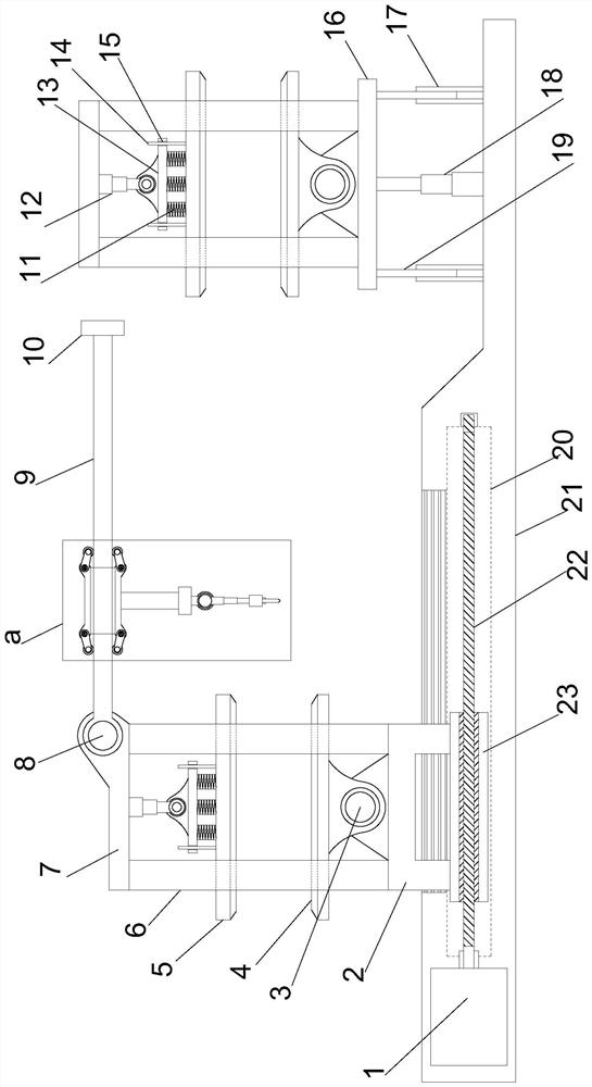
[0028] see Figures 1 to 3 , In the embodiment of the present invention, an orthopaedic drilling guide aiming device includes a support mounting plate 21, and also includes:
[0029] Two sets of rotating clamping mechanisms; and the two sets of rotating clamping mechanisms are respectively arranged at both ends of the support and mounting plate 21; the supporting and mounting plate 21 cooperates with the rotating clamping mechanism at one end to be provided with a moving displacement mechanism, and the rotating clamping mechanism The mechanism is provided with a displacement drilling mechanism; the support mounting plate 21 is provided with a guide lifting mechanism in cooperation with the rotation clamping mechanism at the other end.
[0030] The movement and displacement mechanism includes a support guide groove 20, which is arranged in the support installation plate 21, and a guide screw 23 is slidably disposed inside the support guide groove 20. One end of the support guid...
Embodiment 2
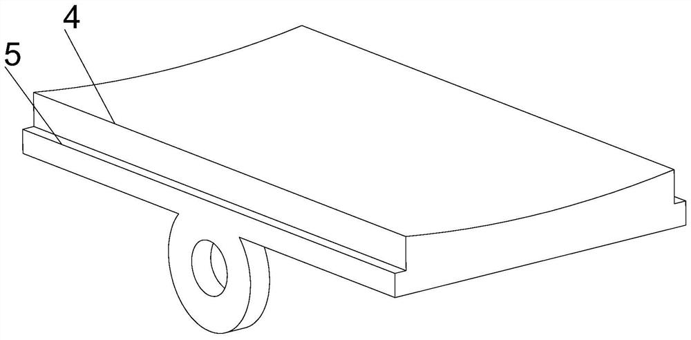
[0034] On the basis of the first embodiment, the rotating clamping mechanism includes a top mounting plate 7 , two ends of the top mounting plate 7 are symmetrically provided with support mounting brackets 6 , and a clamping mounting plate is arranged between the support mounting brackets 6 facing each other. 5. The sponge 4 is provided on the side facing the clamping mounting plate 5, and the top mounting plate 7 facing the clamping mounting plate 5 on one side is provided with an electrically controlled telescopic column 12, and the outer end of the electrically controlled telescopic column 12 is provided. A swinging mounting plate 13 is provided on the rotating shaft, and the swinging mounting plate 13 and the opposite clamping mounting plate 5 are connected by springs 11 arranged in an array. The four corners of the swinging mounting plate 13 are provided with elastic guide holes 15 to clamp the mounting plate. 5. The elastic guide holes 15 are provided with elastic guide p...
Embodiment 3
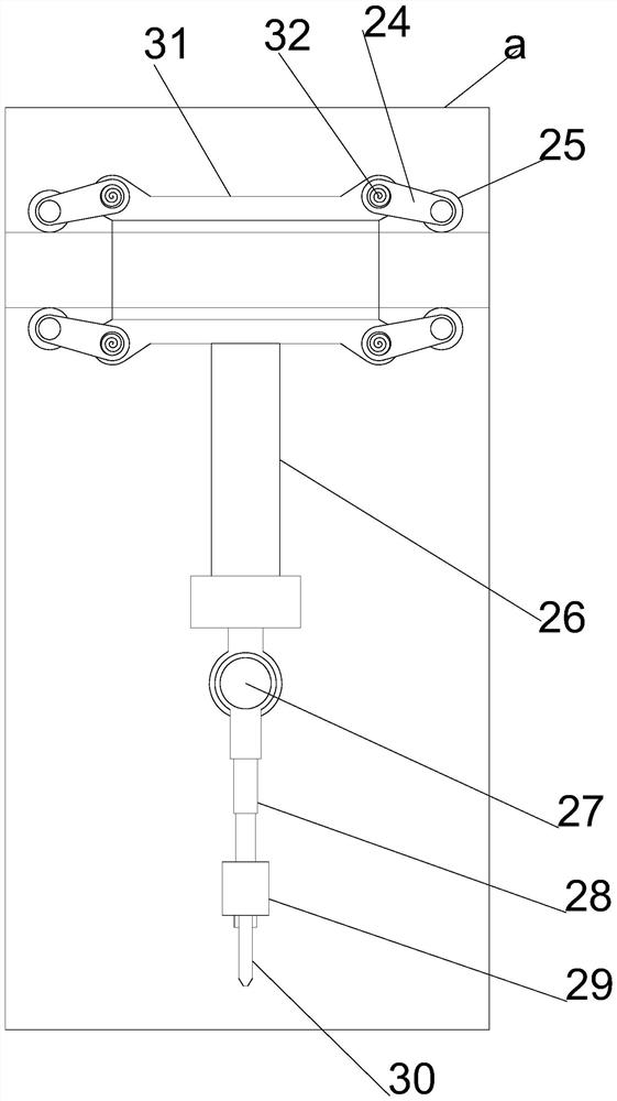
[0037] On the basis of the second embodiment, the displacement drilling mechanism includes a swing guide column 9 provided at one end of the top mounting plate 7 , and a guide installation cylinder 31 is provided on the swing guide column 9 , and a guide installation cylinder 31 is provided on one side of the guide installation cylinder 31 . The installation column 26 is fixed, the outer end of the fixed installation column 26 is provided with a swing telescopic column 28 through the working rotating shaft 27, the outer end of the swing telescopic column 28 is provided with a drill bit 30 through the driving motor 29, and one end of the swing guide column 9 passes through the driving rotating shaft. 8 is connected to the top mounting plate 7, the other end of the swing guide column 9 is provided with a limit block 10, both ends of the guide installation cylinder 31 are symmetrically provided with a reset swing frame 24, and one end of the reset swing frame 24 passes through the ...
PUM
 Abstract
Description
Claims
Application Information
 - R&D
- Intellectual Property
- Life Sciences
- Materials
- Tech Scout
- Unparalleled Data Quality
- Higher Quality Content
- 60% Fewer Hallucinations
Browse by: Latest US Patents, China's latest patents, Technical Efficacy Thesaurus, Application Domain, Technology Topic, Popular Technical Reports.
© 2025 PatSnap. All rights reserved.Legal|Privacy policy|Modern Slavery Act Transparency Statement|Sitemap|About US| Contact US: help@patsnap.com


