Al technical title is built by PatSnap Al team. It summarizes the technical point description of the patent document.
A technology for metal pipe fittings and bending devices, which is applied in the field of U-shaped metal pipe fittings bending devices, can solve the problems of large energy consumption, large size, inapplicability, etc., and achieves improved stability and service life, simple device structure, and improved practicality. sexual effect
Inactive Publication Date: 2021-07-09
刘晓慧
View PDF0 Cites 1 Cited by
Summary
Abstract
Description
Claims
Application Information
AI Technical Summary
This helps you quickly interpret patents by identifying the three key elements:
Problems solved by technology
Method used
Benefits of technology
Problems solved by technology
[0003] When using the existing metal pipe fittings, in order to adapt to different use environments, it is usually necessary to bend the metal pipe fittings. For the bending of the pipe fittings, a bending device is usually used for bending. It is large and requires electric drive, which consumes a lot of energy, resulting in high cost, and is not suitable for small workshops. At the same time, the existing bending devices generally use rigid clamping, which is easy to scratch the workpiece and cause damage to the workpiece
Method used
Image
Click on the blue label to locate the original text in one second.
Reading with bidirectional positioning of images and text.
Examples
Embodiment Construction
[0021] The present invention is described in further detail now in conjunction with accompanying drawing. These drawings are all simplified schematic diagrams, which only illustrate the basic structure of the present invention in a schematic manner, so they only show the configurations related to the present invention.
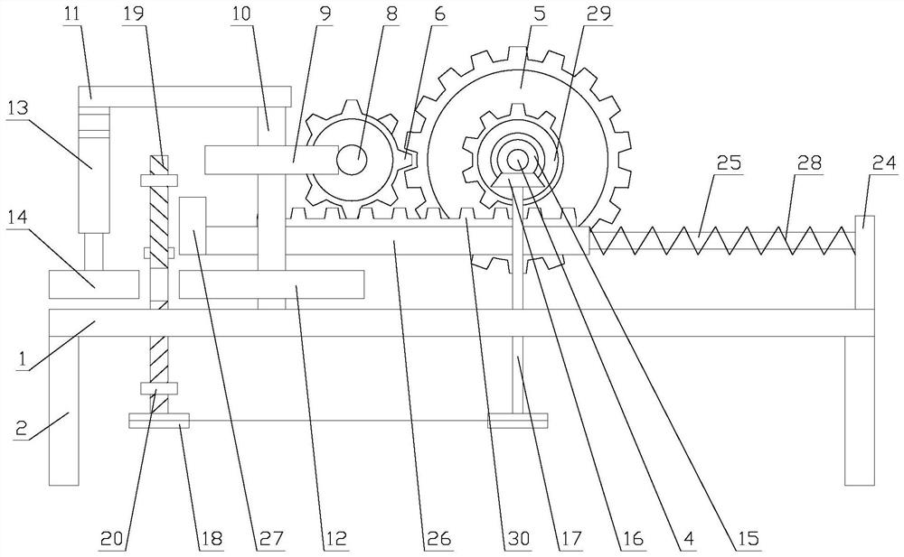
[0022] Such as figure 1 As shown, a U-shaped metal pipe bending device includes a base 1, a support rod 2, a bending mechanism, a clamping mechanism and a pushing mechanism. There are two support rods 2, and the two support rods 2 are respectively arranged on Both ends of the base 1, the bending mechanism, the clamping mechanism and the pushing mechanism are all arranged on the base 1;
[0023] When the device is in use, the workpiece is clamped by the clamping mechanism, the workpiece is bent by the bending mechanism, and the material is pushed by the pushing mechanism.
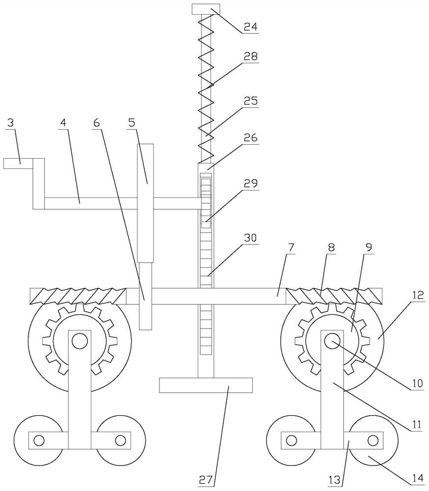
[0024] Such as figure 2 As shown, the bending mechanism includes a driving assembly ...
PUM
Abstract
The invention relates to a U-shaped metal pipe bending device. The device comprises a base, supporting rods, a bending mechanism, a clamping mechanism and a pushing mechanism, two supporting rods are provided, the two supporting rods are arranged at the two ends of the base separately, and the bending mechanism, the clamping mechanism and the pushing mechanism are all arranged on the base. According to the U-shaped metal pipe bending device, the clamping mechanism is used for clamping a workpiece, the bending mechanism is used for bending the workpiece, the pushing mechanism is used for discharging the workpiece, and compared with an existing bending device, the device is simple in structure, convenient to overhaul, free of electric drive, low in cost and suitable for being used in small workshops; and the bending mechanism and the clamping mechanism are in linkage, and thus on-line clamping of the workpiece is realized; meanwhile, the linkage adopts a pure mechanical structure, the stability of the device is improved, and the service life of the device is prolonged; and compared with an existing clamping mechanism, the mechanism adopts flexible clamping, the situation that the workpiece is scratched due to rigid clamping is avoided, the workpiece is protected, and the practicability is improved.
Description
technical field [0001] The invention relates to a U-shaped metal pipe fitting bending device. Background technique [0002] Metal pipe fittings are important components in the connecting pipelines of modern industrial equipment. They have the properties of high temperature resistance, low temperature resistance, aging resistance and corrosion resistance, so they are widely used. [0003] When using the existing metal pipe fittings, in order to adapt to different use environments, it is usually necessary to bend the metal pipe fittings. For the bending of the pipe fittings, a bending device is usually used for bending. Large, and requires electric drive, consumes a lot of energy, resulting in high cost, and is not suitable for small workshops. At the same time, the existing bending devices generally use rigid clamping, which is easy to scratch the workpiece and cause damage to the workpiece. Contents of the invention [0004] The technical problem to be solved by the prese...
Claims
Application Information
Patent Timeline
Application Date:The date an application was filed.
Publication Date:The date a patent or application was officially published.
First Publication Date:The earliest publication date of a patent with the same application number.
Issue Date:Publication date of the patent grant document.
PCT Entry Date:The Entry date of PCT National Phase.
Estimated Expiry Date:The statutory expiry date of a patent right according to the Patent Law, and it is the longest term of protection that the patent right can achieve without the termination of the patent right due to other reasons(Term extension factor has been taken into account ).
Invalid Date:Actual expiry date is based on effective date or publication date of legal transaction data of invalid patent.